This thread has been locked.

If you have a related question, please click the "Ask a related question" button in the top right corner. The newly created question will be automatically linked to this question.

DP83822I: configuration of LED_0

Part Number: DP83822I

Dear Specialists,

My customer is considering DP83822 and has a question.

I would be grateful if you could advise.

---

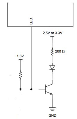
I am considering LED_0 circuit.

In this case, VDDIO is 1.8V, AVD is 1.8V.

I'd like to use open drain and LED drives 3.3V.

Is it possible to use this configuration.

Plus, could you please advise the other point to consider.

ーーー

I appreciate your great help in advance.

Best regards,

Shinichi

  • Hello Shinchi,

    Are you using 3.3V on the LED to ensure that the voltage is enough for the LED to glow? If the VDDIO is 1.8V and the LED needs to operate at 3.3V, you shouldn't connect the two rails like that. I would recommend using a transistor isolation between the strap pin and the LED as shown below,

    -Regards,

    Aniruddha

  • Hi Aniruddha,

    Thank you for your reply.

    I understand when VDDIO is 1.8v, it is not recommended LED_0 drives 3.3V LED directly.

    I'll share your provided circuit with the customer.

    I appreciate your great help.

    Best regards,

    Shinichi

  • Hi Aniruddha,

    I sent your advice to the customer.

    He has additional question.

    I would be grateful if you could advise.

    ---

    About LED drive circuit with transistor, LED is ON when  LED_0 is 1 and LED is off when LED_0 is 0.

    In this case, could you please advice the following questions?

    (1) STRAP Mode=4 (According to the datasheet, the outside pullup resistor value is depended on which is useing the internal pullup or pulldown. But I can't find how to select. Please tell me recommended value.) 

    (2) LED_CFG(0) =1 at TABLE 12.  (I think this means LED_CFG=1 at TABLE 10 . Is it correct?) 

    (3) When initializing the PHY at start up, LED_0 may become unknown and is there a possibility to light up the LED ?

    ---

    I appreciate your great help and cooperation.

    Best regards,

    Shinichi

  • Hi Aniruddha,

    This is just a friendly reminder that I’m waiting for your reply about additional questions. 

    I appreciate your great help and cooperation.

    Best regards,

    Shinichi

  • Hello Shinchi,

    Please find my replies below.

    1. For selecting strap resistor for a Strap pin on DP83822, first identify what Mode of strapping (1, 2, 3, or 4) will give you the desired functionality. Then check if the strap pin has a internal pull up or pull-down. This information is available in Pin function table of the datasheet. Next check Recommended Strap Resistor ratio table in the datasheet to identify which resistor you need to use. This table is divided in two section, one for pins with internal pulldown resistors and other section for pins with internal pullup resistors. Select the values depending on the pins that you want to use.

    2. You are correct. 'LED_CFG' from table 10 is the 'LED_CFG[0]' in table 12.

    3. As described in the datasheet LED pins need a pull resistor for proper operation. If you want LED_0 to be strapped to mode 1, then use a pull-down resistor and if you want it to mode 4 then use a pull-up resistor. Resistor value can be between 1.96kohm to 2.49kohm for both modes. After doing this, the LED should not light up.

    -Regards,
    Aniruddha
  • Hi Aniruddha,

    Thank you for your reply.

    I'd like to reconfirm to you.

    Question (3) is for during intialize condition.
    In this case, how is the output, H, L, or HiZ ?
    Is there a possibility of LED lighting up?

    Best regards,
    Shinichi