This thread has been locked.

If you have a related question, please click the "Ask a related question" button in the top right corner. The newly created question will be automatically linked to this question.

DS250DF410: DS250DF410

Part Number: DS250DF410
Other Parts Discussed in Thread: SIGCONARCHITECT

Hi Ti

We are using DS250DF410 based backplane and mid-plane applications.

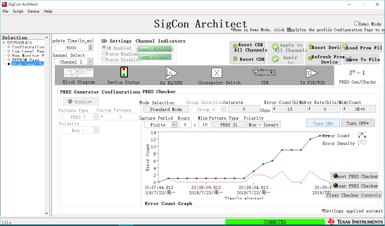
According to the configuration requirements on page 10 of ds2x0dfx10snlu182 programmer guide, we found that CDR was not locked.

In the document, we cannot confirm how to adjust the parameters. Is there any adjustment of the configuration parameters based on the backplane and linecard routing parameters?

  • Greetings,
    1). I am assuming you are operating the device at 25.78125Gbps data rate? Otherwise please let us know the operating data rate. Also, please send me your complete register settings plus register read backs.
    2). Can you please use SigconArchitect GUI to control DS250DF410 device? Once this is done, please send me your complete register dump.
    Regards,,nasser
  • Could you provide profiles updates for DS250DF410

  • We refer to the following configuration to set the parameters。

    The registers read back

    read reg 0xF1
    *******************************
    HEX:      10
    DEC:      16
    BIN:      00010000
    *******************************

    read reg 0xFC
    *******************************
    HEX:      8
    DEC:      8
    BIN:      00001000
    *******************************

    read reg 0xFF
    *******************************
    HEX:      3
    DEC:      3
    BIN:      00000011
    *******************************

    read reg  0x00
    *******************************
    HEX:      0
    DEC:      0
    BIN:      00000000
    *******************************

    read reg  0x0A
    *******************************
    HEX:      0
    DEC:      0
    BIN:      00000000
    *******************************

    read reg  0x2F
    *******************************
    HEX:      54
    DEC:      84
    BIN:      01010100
    *******************************

    read reg  0x31
    *******************************
    HEX:      60
    DEC:      96
    BIN:      01100000
    *******************************

    read reg  0x1E
    *******************************
    HEX:      e3
    DEC:      227
    BIN:      11100011
    *******************************

    read reg  0x3D
    *******************************
    HEX:      8f
    DEC:      143
    BIN:      10001111
    *******************************

    read reg  0x3F
    *******************************
    HEX:      40
    DEC:      64
    BIN:      01000000
    *******************************

    read reg  0x3E
    *******************************
    HEX:      43
    DEC:      67
    BIN:      01000011
    *******************************

    read reg  0x0A
    *******************************
    HEX:      0
    DEC:      0
    BIN:      00000000
    *******************************

  • Greetings,

    1). Please follow the link below to get DS250DF410 updater plus other design documents such as data sheet, high speed modeling, schematic, and etc.
    myportal.ti.com/.../dt

    2). Using SigconArchitect, there is a setting in CDR tab where you can manually dial in the desired data rate. Then you can sue the register settings for you own device. Please first try this software to make sure you can lock to your desired data rate.

    Regards,,nasser
  • hi

    I get the DS250DF410 updater now,and my CDR is locked,figure blow.

    When we were doing the PRBS 32 test, we found many bit errors.Meanwhile, if we change prbs32 to prbs15, there will be no bit error.

    The parameters in the diagram, how do we debug them now?Do you want to adjust the parameters of TX or change the RX of the retimer to manual mode (now mode2 adapter)?

  • Greetings,
    It is preferred to have HEO greater than and equal to 0.45UI. I noticed there are some channels with 0.37UI of eye opening.

    1). When you get bit error with PRBS31, you have bit errors on all CDR channels or just perhaps CDR with 0.37UI HEO?

    2). What is the value of AC coupling capacitor you are using? Do you get bit error if you increase your AC coupling capacitor value?

    3). Please send us a picture of RX EQ/DFE tab.

    4). Also, it would be a good idea if you could please let us know signal path from your ASIC to the DS250DF410 device.

    Regards,,nasser
  • hi ti

    Please see the attachment for reply.

    report.docx

  • Greetings,

    Thanks very much for sending these detailed information.

    In general we should optimize register settings in order to make sure we are getting at least a HEO of 0.44UI and VEO greater than 200mV.

    After reviewing your block diagram, we have some recommendations:
    1). In order to optimize DFE and other settings to optimize eye opening, we should do green box analyses. Please note URL below describing this in more details:
    www.ti.com/.../slyt678.pdf
    2). Since signal goes through two connectors, backplane, and line card it is best for the switch to have high VOD of about 800mV.
    3). Switch or ASIC should provide pre cursor of -3 to -6 which is about 3 to 5dB
    4). Switch or ASIC transmitter should have no post cursor since this may cause over equalization.
    5). It is best to sweep pre and post cursor and do green box analyses. This should be done with a pass criteria of 1e12 to 3e12 BER.
    In summary, steps 1 through 5 should be taken to achieve optimized HEO and VEO numbers(HEO>0.44 and VEO > 200mV).

    Looking at your SigconArchitect settings, please make sure you reset CDR after changing AM2 or manual settings. For example, you should enable AM2, then hit Apply and finally click on reset CDR. Otherwise, CDR will not report correct HEO/VEO settings.

    Could you please let us know what is the insertion loss on signal path? Or signals arriving on DS250DF410 device.

    Regards,,nasser
  • hi Nasser

    Thank you for your reply,my reply is as follows

    1). In order to optimize DFE and other settings to optimize eye opening, we should do green box analyses. Please note URL below describing this in more details:
    www.ti.com/.../slyt678.pdf

    [wind]Green-box testing requires software to write script tests which takes a long time. We will arrange it as soon as possible. 
    2). Since signal goes through two connectors, backplane, and line card it is best for the switch to have high VOD of about 800mV. 
    3). Switch or ASIC should provide pre cursor of -3 to -6 which is about 3 to 5dB
    4). Switch or ASIC transmitter should have no post cursor since this may cause over equalization.

    [wind] As for the requirements of 2, 3 and 4, our current TX parameter is basically the same as yours.As shown in the figure below, we configure pre-cursor around 2dB


    Now I configure AM3, will it be very different from AM2?In my tests, I found no difference between the two

  • Hi Wind,

    AM3 configuration is good for when insertion loss is less than 25dB and there is a heavy cross talk. In this mode, DFE adapts with minimal CTLE settings. On the other hand, AM2 configuration is good for cases when insertion loss is greater than 25dB and there is heavy cross talk. In this mode, DFE adapts after CTLE adaptation. As you can see, DFE is used to counter cross talk effects. Finally, in AM1 CTLE is adapted when there is no cross talk and insertion loss is less than 25dB.

    1). What is insertion loss of your connectors plus the back plane?
    2). Please use AM0, AM1, AM2, and AM3 to find optimum CTLE settings which optimizes HEO/VEO parameters. Essentially this is the same as green box analyses that you are planning to do.

    Regards,,nasser

  • hi Nasser

    1). What is insertion loss of your connectors plus the back plane?

    [wind]The line insertion loss shall not exceed 10dB

    During the debugging process, I will debug the parameters of RX end to your recommended range, as shown in the figure below.But I found a bit er'ror in the PRBS test.How do I adjust the parameters?

    Why is it that the center of the eye is not at zero during the eye monitor test?

  • Hi Wind,

    What you are seeing regarding eye diagram I believe is normal. This is due to the fact you are turning on DFE. Please use either AM1 or AM0 and I don't expect to see this in your eye diagram.

    Also, to get error free operation we need to do green box analyses which I believe you are working on this.

    Regards,,nasser