This thread has been locked.

If you have a related question, please click the "Ask a related question" button in the top right corner. The newly created question will be automatically linked to this question.

Linux/DP83867IR: IT LAN LAN up/down issue support--Urgent!

Part Number: DP83867IR

Tool/software: Linux

Our customer meets an emergency issue and need help!

Their company have a RSB-468 project and product 15pcs, and find 6pcs LAN up/down fail. The specific description is:
Disable LAN and then Enable LAN,LAN would have no function, must reboot or enable many times then the function is OK.
(TI LAN PHY DP83867IRRGZT)

1. User environment: android6.0 (kernel3.10),if config eth0 down/up, then will meets the problem randomly.     

2. Their engineer configed register like this:

        //address mask value

        0x0014 0x200 0x200

        0x0018 0xfff 0x65b

        0x001e 0x200 0x200

        0x0032 0x3 0x3

        0x0086 0xff 0x80

        0x0170 0x1f00 0x0000

  • Hi Chen,

    Do you have a schematic for the design? I would like to see your schematics.

    Best Regards,
  • Hi Chen,

    Thank you for the schematic. I have some notes:

    From your schematic, the CLK_OUT of the DP83867 is being routed to the MAC. The register configuration shows ch A recovered clock is being sent to the MAC. What are the requirements for the clock into the MAC?

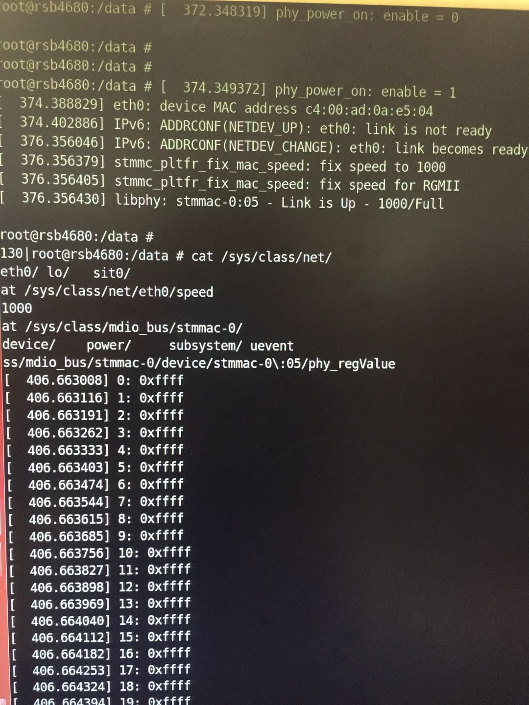
    Also, can you give me a screenshot of how the connection is failing? I cannot tell if the failure is by link bit, register access, or data into the MAC.

    Please provide register values during failure, of register address 0x0 to 0x1f, and include 0x32, 0x86, 0x170

    What kind of cable is being used? Are all 4 pairs in the cable? What link partner is being connected to the DP83867?

    A photo of the setup would be good, as well as a video if possible.

    Best Regards,
  • Set eth0 down, then up, no LAN linked to 1000M

    The 18th  pin CLK_OUT connected to CPU as a reference clock of GMAC inside;
    the config platform is ARM+DP83867.

    The register is:
    0x006E:0x5

    0x006F:0x100

    When failing, the register is 0xffff

  • The block diagram is like this, the information about NETWORK is using A/B/C/D 4 pairs of LANs in 1000M case; using A/B 2 pairs of LANs in 10M and 100M cases.

  • Hi Chen,

    Thank you for the information.

    If the PHY is responding with all F's to a register read, then something is wrong with the communication between the PHY and the MAC. Either the PHY is in reset, or powered off, or the PHY is not at the PHY ID being reached. The indication that the link is down may not be accurate because MDIO is not working in this case.

    I am not a Linux/Android expert, so I am not clear on how ifconfig disables the DP83867. If it disables the PHY by strobing the RESET line or holding the RESET line to the PHY, with data on the RGMII present, then the DP83867 is likely strapping into a different PHY ID.

    If you have current limiting resistors in line with the RGMII signals, then these can be removed and you can test this behavior. With the current limit resistors removed, the DP83867 should strap into the same PHY ID during every reset pulse.

    Best Regards,
  • Hi, Rob

    Thanks for your help, the customer gives some explanation about the functions:


    Disable means pull down the 43th pin of PHY, so makes PHY in reset mode,Enable means releasing reset.

    And about PHY Address mode,as the schematic provided before shows,there is no pull up or pull down resister with RX_D0 and RX_D2,and the status are all open as the page 46 in datasheet recorded, it also means PHY_ADD3/2/1/0 of Level Strap is 0000 set by HW. 

    At Default status,reset is always high and no pull down operation,SW is 00,and it's PHY_ADD3/2/1/0 is 0000。

    But when reset is pulled down,the voltage of RX_D0 and RX_D2 is about 200mV,so it's between mode0 and mode1,and SW is 05,so it's PHY_ADD3/2/1/0is 0101,What's the reason of this?

    Attached is Trigger Reset's waveform is from Disable to Enable.  Best Regards.

  • Hi Chen,

    "But when reset is pulled down,the voltage of RX_D0 and RX_D2 is about 200mV"

    This is probably caused by an internal pull-up resistors on the connected MAC pins. The DP83867 has internal pull-down of 9k. Seeing that the voltage a RX_D0 is ~200mV, that would indicate the RK3288 has internal pull-up equivalent ~72k on these lines since VDDIO = 1.8V.

    Best Regards,
  • Hi Rob,

    The customer updated their issue:
    RK3288 MAC has a pull up Resistor, and the range is as following, so how to insure PHY_ID of TI_83867 not modified after reset?

    And they have tried PHY_ID from 0000~1111 in a same board (inner pull up resistor is 72KΩ), and find that the if including mode1 (0000/0001/0010/0011/0100/1000/1100), PHY_ID will be modified after reset.

    And with the pull up resister range in MAC, in addition with pull down resister is 9K±25%(6.75K~11.25K) as the datasheet about TI_83867, it’s really difficult to verify each situation,
    so if there is a practical solution in PHY_ID=0000?

    For example:
    Combination 1: CPU Rpu=100K, PHY Rpd=9K, voltage is 0.149V when opened, and PHY_ID is normal when reset in mode1 range.
    Combination 2: CPU Rpu=50K, PHY Rpd=10K, voltage is 0.3V when opened, and PHY_ID is abnormal when reset in mode2 range.

    Best regards
  • Hi Rob,

    Our customer verified a solution, but they need to evaluate the feasibility and risk, so I really need your help.

    During boot procedure:

    Old solution:boot,Pull up Reset and PWDN hardware control bit. Then pull down the Reset and release Reset to high after CPU initialization and before config PHY.

    Modified solution:boot,Pull up Reset and PWDN hardware control bit. No pull down operation of SW.

    Operation in system:

    Old solution:Disable is to pull down the 43th pin Reset of PHY to make PHY in reset mode, Enable is to release Reset.

    Modified solution:Disable is to pull down the 44th pin PWDN of PHY to make PHY in PWDN mode, Enable is to release PWDN.

    Best Regards.