This thread has been locked.

If you have a related question, please click the "Ask a related question" button in the top right corner. The newly created question will be automatically linked to this question.

Strange problem with MAX3232 (noise on 3.3v rail)

Other Parts Discussed in Thread: MAX3232, MAX3223, MAX232


I have been using the same basic design on many boards, which consist of the following:

- MSP430

- Switcher for 5v and LDO down to 3.3v

- MAX3232 for serial peripherals

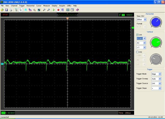
Till now I have not had a problem, but lately one has arose. The issue is that when I connect an external RS232 device to the MAX3232, there is a lot of noise on the 3.3v rail to the extent that it interferes with the I2C and SPI communications.

Attached are some scope grabs and the schematic for the power section. The use of the MAX3232 is by the book (i.e. all caps are 0.1uF).

Why would the external RS232 connected to one side of the MAX3232 be causing fluctuations on the 3.3v rail and interferance on other logic lines?

By the way, I am only using the MAX3232 because it is 3.3v (so it can connect to the MSP). I do have a 5v rail on the board also. Should I be using another line driver?

7433.3.3v rail testing with LDO, External PS, and RS232.rar

  • Gracufl,

    Thank you for the detailed information and many waveforms. This was a great help to me.

    Some noise on the 3.3V line is expected because the capacitor charge pump is noisy by nature. The noise can be reduced by adding more (low ESR) bypass capacitance at the MAX3232. The MAX3232 charge pump runs as needed and it usually only take one cycle to recharge the pump. The heavier the load, the more frequently the pump runs.

    The larger noise is caused low phase margin of the LDO. It appears to be oscillating at a frequency much different than the charge pump noise when powered by the SMPS. Verify that the output capacitors are within the recommended range of the LDO.

    Regards,
    Ron Michallick


  • Thanks Ron.

    Well, I have been having doubts about the LDO. It is a MIC5209 and the datasheet says ""The output capacitor should have an ESR (equivalent series resistance) of about 1ohm and a resonant frequency above 1MHz. Ultra-low-ESR capacitors can cause a low amplitude oscillation on the output and/or underdamped transient response.".

    Sounds like I might be better off looking for another part. Can you suggest a TI LDO for 3.3v ?

    By the way, should I be looking for another line driver? The only reason I am not using MAX232 is that I am using the MSP and 3.3v TTL logic. I have a 5v rail and can possibly look at another part. I recently heard of the MAX3223 but have yet to really understand the difference between that and the MAX3232.

    Thanks!


  • Gracufl,

    The MAX3223 is a MAX3232 with extra features added.
    The receivers and drivers can be disabled manually or automatically.
    An extra logic output goes low when all receivers have no input signal.

    The TLV1117LV33 is very low cost and states that it is stable with low ESR ceramic capacitors.

    Regards,
    Ron Michallick

  •  

    Hi Ron,

    I did some more testing, basically did two things:

    1. Populated a LDO only on to my newest version of the board and found it to be clean (5mV ripple, acceptable I think)

    2. Testing with a previous version of the board that uses same LDO and MAX3232 - got a 80mV ripple when the RS232 is connected and a little less when it is not connected

    So, it is clear that the MAX3232 is causing this noise on the 3.3v rail (and probably the source of my other I2C/SPI noise related issues as well). The question is, what to do and does it have to be like this. I understand that the MAX3232 uses charge pumps, but to they have to tug on the rail like that?

    By the way, the TLV1117LV33 is out of stock on most sites... (but anyway, while I am most willing to change LDO, I don't think that's the issue here)

    Thanks


  •  

    OK.... issue identified and basiclaly solved.....

    The MAX3232, when RS232 plugged in, was introducing too much noise on the Vcc line. This cause one of the components on the board to fail in such a way that it could still be communicated with over SPI but it did not do its job (basically an RF module, the noise was enough to screw up the receiver).

    My question now is - how can I prevent this noise from the charge pumps of the MAX3232 from coming on to the Vcc line??


  • Gracufl,

    Noise that the same frequency as the charge pump (pin3 clock  for example) is MAX3232 related, if it is a different frequency then the cause is elsewhere.
    That being said, I powered up the MAX3232 using just the data sheet caps. I also put 3k loads on both drivers to get the noise level up.

    I observed great reduction in noise by adding a 10uF or larger ceramic X5R capacitor in parallel with the VCC bypass capacitor.
    Also helpful was a 5 ohm series resistance with the 3.3V supply voltage.
    The MAX3232 has less noise when V+ capacitor was terminated at VCC.

    Regards,
    Ron Michallick


  • Ron Michallick said:

    I observed great reduction in noise by adding a 10uF or larger ceramic X5R capacitor in parallel with the VCC bypass capacitor.
    Also helpful was a 5 ohm series resistance with the 3.3V supply voltage.

    Hi Ron. Few questions on this:

    - What should be the ESR of the 10uF cap?

    - Why add a 10uF to the 0.1uF already there? Why not just have the 10uF only?

    - What about replacing the 5 ohm resistor with a ferrite bead? (if so, what should be the rating of such a bead?)

    Thanks

  • I keep coming back to this again and again..... I can't be the only one using a combination of digital circuits and RF..... I am sure that other folks are also using line driver on designs that also use RF components.

    The problem is that without a doubt, the MAX3232 is introducing noise on the Vcc. This is reduced by enlarging the decoupling capacitors but still is present, and moreover it gets worse when an external RS232 device is connected (i.e. when the line driver is actually driving).

    This noise basically messes up the receiver of the RF module we are using and prevents it from working properly.

    So again, how to prevent the MAX3232 from screwing up the Vcc? If it is not used, I get a very nice 5mV ripple which is fine. But when they are used, ripple is 10-60mV!

    There has to be a way to isolate these trouble makers.....

  • Gracufl,

    If the 10uF cap is low ESR then the 0.1uF cap won't add much benefit. 0.1uF caps general have a higher self resonant frequency than a 10uF cap so the parallel pairing increases the frequency range of the capacitive action.

    Lower ESR is beneficial , but I do not have specific value in mind.

    Would consider using an series inductor? If so, I will test a few.

    Regards,
    Ron Michallick


  • Hi Ron. Actually, as far as testing, if you like it would be great if you could try something which was suggested to me but I can't try yet as the PCB does not allow. It was suggested, that a resistor be added in series with the C1 (~47ohm). Presumably that helps also.

  • Gracufl,

    The noise benefit for a C1 resistor is minor. I would not use more the 10 ohms. At 33 ohms the charge pump ran all the time just for the 3k loads on the drivers not including capacitive load while switching.

    I tested a 5 and 10 ohm resistors in series with VCC line with caps on both side of resistor.

    So far, larger caps on VCC and optional VCC series resistor are the most effective for supply noise reduction.

    Regards,
    Ron Michallick