This thread has been locked.

If you have a related question, please click the "Ask a related question" button in the top right corner. The newly created question will be automatically linked to this question.

RS485 common mode disturbances

Other Parts Discussed in Thread: SN65HVD20

I would appreciate some help from you regarding the following issue:

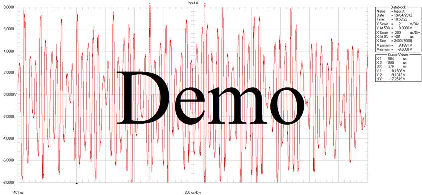
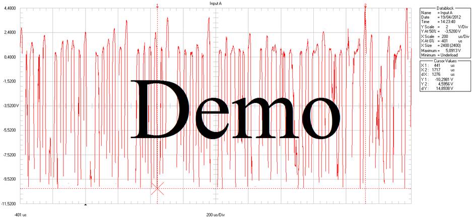
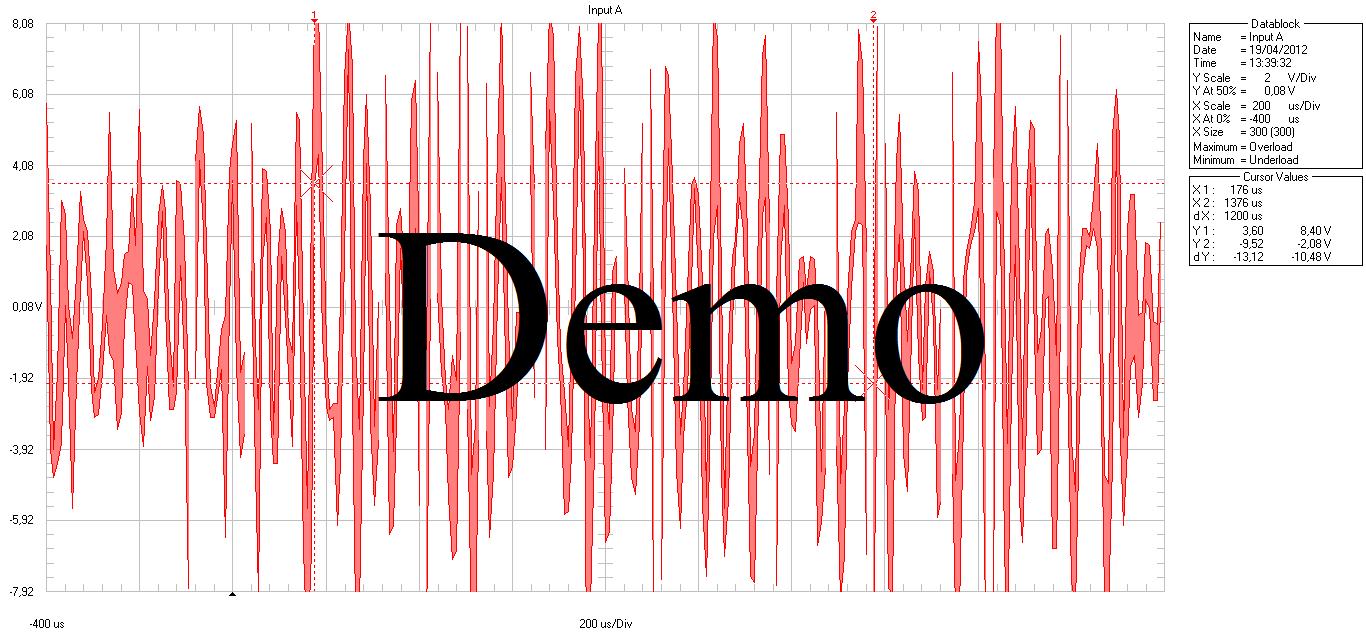
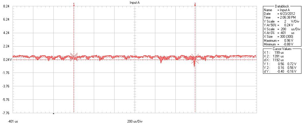
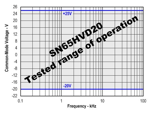
We have performed an analysis of the communication buses through a Moxa MGate COM1 and COM2. I attach the signal in common mode registered, this is not a punctual case but the disturbances are continuous. As you can see, there are voltage peaks of -9V and +8V with frequencies of more than 40kHz. We have detected at least one burned component per RS485 port: the transceiver SN65HVD20. Our objective is to be able to prove our client that the transceivers are manufactured under industrial standards and this is an abnormal disturbance capable of burning the SMD’s. Do you have any study that tests the SN65HVD20 under extreme voltages and frequencies such as the ones registered?

I appreciate your help. Thanks in advance. Julio.


  • we are looking into this. The HVD20 must be able to withstand up to +/- 27V common-mode voltage.

    could you please provide a schematic of how and where this signal is measured?

    Thank you, Thomas

  • I also want to point out that to avoid large high-frequent common-mode signal, you can apply common-mode filtering by replacing the 120 W resistor through two 60 W ohms resistors and connecting a 680 nF capacitor between the middle-tap and ground.

    It's a 1st order low-pass with fc = 4kHz.. Its 20dB roll-off per decade should attenuate your 40kHz signal by about 90%.

    Please encourage your customer to try this first.

    Regards, Thomas

  • Hi Thomas,

    I really appreciate your help. We have installed an 120ohm resistor + 47nF 63V capacitor between Data+ and Data- and is attenuating acceptably the high frequency disturbance.

    The signal (which graph I sent you) was measured in the RS485 port COM2 of a Moxa MGate MB3280, between Data+ and Data-. This port communicates with up to 20 string boxes in serial.

    We presume the disturbance is due to the bad quality of the communication cable (Draka FTP Cat.5e) and the field installation of this cable (in parallel with medium voltage cabling coming from the inverters), both factors responsibility of our client.

    The fact is the SN65HVD20 is burnt; we should show our client a certificate from Texas Instruments indicating the SN65HVD20 is capable of withstanding, in common mode, frequencies up to X kHz with voltage peaks between A and B Volts (X < 40kHz; A < -20V; B < +25V).

    Thanks again for your support.


  • Julio,

    AC termination, the termination you are using, is famous for "butchering" line signals. the choice of the capacitor is NOT trivial and depends on the number of bus nodes, the cable length, and the data rate. while from my side I will be digging into the test and certificate availability for the HVD20, could you please do me the favor and bypass the capacitors (I'm assuming you terminate both cable ends) for a signal measurement. I would like to see the signal distortions with only the 120 ohms present.

    Thank you,  Thomas 

  • Hi Thomas,

    In fact, we have tried several capacitors (120nF 63V, 100nF 50V and 47nF 63V), the best results obtained with the 47nF 63V between Data+ and Data-, installed in the last RS485 node.

    Please find several graphs measured in the RS485 port COM2 of the Moxa MGate MB3280:

    Common mode between Data+ and Data- with a 120ohm end of line resistor (graph sent in my first mail)


    Common mode between Data+ and earth with a 120ohm end of line resistor


    Common mode between cable shield and earth with a 120ohm end of line resistor


    Common mode between Data+ and Data- with: a 120ohm+47nF end of line and a Moxa TCC-120I optoisolator

    I look forward to receving the HVD20 certificate.


    Thanks, Julio.

  • Julio,

    the high common-mode voltages specified in the data sheet were tested with DC voltage. To do a high-voltage AC-test up to +/- 20V, I had to order new components to design a new common-mode test-amplifier. The components will hopefully arrive Friday so that we can do the test on Monday.

    So far we have tested only the standard common-mode voltage range of Vcm = +/- 7V AC up to 100 kHz and the HVD20 continues to work perfectly!

    Regards, Thomas

  • Julio,

    the SN65HVD20 was tested in a point-to-point communication link for common-mode failures over a common-mode voltage range from -20V to +25V and over a frequency range from DC to 100 kHz. Across the entire range the SN65HVD20 performed failure free without any significant increase in device temperature.

    An additional test with regards to bus contention was performed. Here both transceivers were configured as drivers with opposite output polarity accessing the bus at the same time. Both transceivers performed as expected. At first the transceivers' internal current limiters kicked in until the internal temperature shut-down functions reacted switching both transceivers off. The bus contention was maitained for 2 hours without any device damage occurring.

    This proofs that the SN65HVD20 is a very robust device.

    Regards, Thomas

  • Hi Thomas,

    I really appreciate your support. Considering the results of your last test, I presume the problem has been because of higher, eventual voltage peaks in the change to signal mode, when the impedance decreases. The problem is we cannot record the signal during say 1 whole day because the analyzer we are using, Fluke Scopemeter 225C, hasn't got this function.

    Thanks again for your kind help.

    Julio.