This thread has been locked.

If you have a related question, please click the "Ask a related question" button in the top right corner. The newly created question will be automatically linked to this question.

SN65HVDA1050A-Q1

Other Parts Discussed in Thread: SN65HVDA1050A-Q1

Hi   you.

Please  give me a reply.

Has  SN65HVDA1050A-Q1  followed up ISO10605 ? 

As follows  No1  and No2

My customer demand a ISO10605  Test-Level4.

This test-level is No1 and No2      

   ・No1:   Discharge for contact  level  8kV.

 ・No2:   Discharge in the air level 15kV.

 ※Regultion:   CR is fixed 150pF ,  2kΩ.


Best regaed      BEN.    from japan.


  • Hi Ben-san,

    Will you be performing the powered DUT testing per ISO 10605?

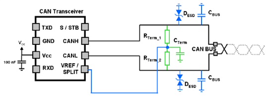
    If so, the SN65HVDA1050A-Q1 device will require external protection to pass at these levels. I recommend placing a NUP2105 or a MMBZ27 from On-Semiconductor as close to the connector on the board as possible (DESD below). In addition, additional bus capacitance will help as well (CBUS below) .

    Depending on whether or not this node will be a terminated node, you can do the active split termination as shown above.

    As with all ESD events, the layout of the board is very critical to the performance of the system. ESD events are very high frequency events and therefore proper high frequency board layout practices should be followed.

    Thanks,

    John

  • Also, we have a next generation CAN transceiver family HVDA551/553-Q1 with enhanced ESD and transient protection built in.  Again this is a system level test and depends on the PCB, Connector, Board Design, Cable assumptions so PCB and external protection options should be planned.  These devices have passed some system level testing requirements for ISO 10605 at certain customers without external protection. 


    -- Scott

  • Hi  John-san

    Thank you for  reply.

    My question is  that  SN65HVDA1050A-Q1  has followed up  ISO10605.

    Your  follow  is  answered.

    Only device be not  followed  ISO10605.

    Your advice will be  follow  circuit  that support  ISO10605.

    It  was  very good  support .

    Thank   BEN.
     

  • Hi Scott -san 

    Thank you for  reply.

    and...

    Thank   you   new  device information. HVDA551/553-Q1.

    I  request  to  HVDA551/553-Q1  from TI's japan  team.

    Thank    BEN.

  • Hi Ben-san,

    Correct, the ISO 10605 is a system level spec, not a device level. We have had customers pass these requirements with good system level layout and protection.

    Please let us know if you have any additional questions.

    Thanks,

    John

  • Hi John-san

    Is  that  right  !

    ISO10605  is a  system level  spec. not  a device level.

    Natural,  I  promote   your supported circuit  for  customer. 

    I  feedback  for  you  that   check  with  my  customer   

    Thanks  BEN  .

  • Hi john-san 

    This   is  BEN.
    I'm sorry   it  takes time  a  litle.    There is  progress  in  the  development.

    There  is  a  possibility  of  applying  32V  CAN-H  by  misconnection,the CAN-L  between
    applications  of  this  time.

    Respectively to the GND,-27V~40V absolute maximum rating CAN-H, CAN-L, of SPLIT ,
    Is it all right in understanding that there is no restriction CAN-H, the CAN-L between?

    For example, if there is any damage as a device to CAN-H 40V, to-27V CAN-L be applied?


    I  think will  not  break.


    Best  Regard         BEN


  • Hi Ben,

    The datasheet recommends that the differential voltage on the bus pins stays within ±7 volts. Therefore, for the condition that you are describing, where there is a fault with a 67 volt (+40 - -27) differential input on the bus pins, the datasheet parameters may not be valid.

    Specifically I think the input leakage current for the receiver will be out of spec. With that being said I do not think that this condition should cause any damage to the device. The minimum differential input resistance for the device is 30kΩ, which means that at 67V differential the device should only be sinking at most 2.2mA. This should not cause any issues.

    Thanks,

    John

  • Also, keep in mind unless you have 2 or more power supplies in the system is it impossible to get such an odd combination.  The -27 to +40V spread would assume 5 faults all at the same time from an automotive viewpoint:

    1) CANH shorted to one power supply

    2) CANH power supply at load dump (40V)

    3) CANL shorted to a separate power supply

    4) CANL power supply reverse polarity

    5) CANL power supply a double battery

    -->  not very likely.  The device will take it but a very non typical case.

    -- Scott


  • John-san.

    Thank you for reply to following.

    I responded my customer, including  the possibility  of  destruction  in  the  comments
    about  the  potential  difference  between  CANH/CANL  for  SN65HVDA1050A-Q1.
    I was  helpful to will  be destroyed at  resistence  value  and  sinking at  most  2.2mA.


    Best  ragard    BEN.


  • Scott-san 

    Thank  you  for  reply and  following.

     I've responded to my customers the possibility of destruction of the use of a car
     for that I received from you

    Best  regard     BEN.