This thread has been locked.

If you have a related question, please click the "Ask a related question" button in the top right corner. The newly created question will be automatically linked to this question.

DP83848K: About External isolation transformer : Common Mode Choke on PHY side or Cable side?

Part Number: DP83848K
Other Parts Discussed in Thread: TIDA-00207,

Hi,

I have questions about an external isolation transformer.

At first, according to "AN-1469 PHYTER Design & Layout Guide"
http://www.tij.co.jp/jp/lit/an/snla079d/snla079d.pdf

=>There is a Common Mode Choke on "Cable" side. 


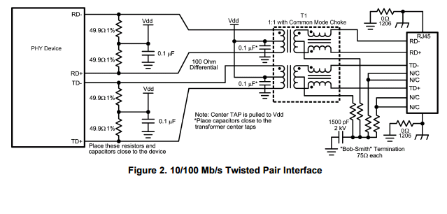
Next, according to "TIDA-00207"(TI design),
www.tij.co.jp/.../tidu515a.pdf

=>There is a Common Mode Choke on "PHY" side.


I have a few questions.
(1) Why is the circuit different?
(2) I think Common mode chock on "Cable" side is usual.
      Why did you change it when TIDA-0027 is designed(Common Mode Choke on "PHY" side. Was this done on purpose?


Best Regards,
Takahiro Ogo

  • Hi Takahiro,

    Typically CMCs are on the cable side like you said above.
    Note sure why the person who designed the TIDA board decided to have the CMC on the device side.
    One possibility is that the board was originally for a TLK PHY and not a DP PHY. The TLK PHYs recommend CMCs on the device side.
    This would explain why the TIDA is different from the datasheet.

    Kind regards,
    Ross
  • Hi Ross, 

    Thank you for your reply.

    I'm a little troubled.
    My customer is using DP83848K and they have already completed their custom board.
    Their schematic is the same as TIDA-00207. So, CMC is on the phy side. Because TI is providing TIDA-00207 as reference board of DP83848K.

    Is there any problem with DP83848K using CMC on the PHY side? 
    Also, does TIDA-00207 board work very well?

    My customer are very worried about this....

    Best Regards,
    Takahiro

  • Hi Takahiro,

    You should not feel troubled.
    There is no issue with having the CMC on either side of the transformer for the DP83848.

    The TIDA board reference works very well.

    Kind regards,
    Ross
  • Hi Ross,

    Thank you for your reply. OK, I understood that. I am a little relieved.

    I would like to ask a question additionally. 
    Are there any advantage to place the CMC on PHY side?
    In other words, are there any disadvantage to place the CMC on PHY side?

    # Placing the CMC on Cable side attenuates any common-mode noise than CMC on PHY side?
    # Placing the CMC on PHY side is strong at ESD? 


    Best Regards,
    Takahiro

  • Hi Takahiro,

    I have not seen a difference between either.
    The only difference you might see is a change in return loss measurement due to the resistance the driver would see with the CMC between the device and the transformer. However, there should not be any affect on functionality and you might not see any difference in return loss. The MDI should still pass regardless of the placement.

    Kind regards,
    Ross
  • Hi Ross,

    Thank you for your kind support! OK, I will tell that to my customer.

    Best Regards,
    Takahiro