This thread has been locked.

If you have a related question, please click the "Ask a related question" button in the top right corner. The newly created question will be automatically linked to this question.

DS92LV2412: DS92LV2411 - DS92LV2412 communication problem

Part Number: DS92LV2412
Other Parts Discussed in Thread: DS92LV2411

Hello,

I have a DS92LV2411 and a DS92LV2412 on one PCB that are functioning properly in BIST mode and with static signals at the input of the 2411.
When applying a signal of about 10kHz the 2412 loses the PLL-LOCK state.
The clock frequency of the 2411 is 5MHz, all strap pins are 0, startup delay of VDD and PDB is 200ms for correct configuration detection.
All supply voltages are blocked, the measured ripple is round about 5mV.

Thanks

Mario 

  • Hi Mario,

    To familiarize myself with your set-up, what is the transmission medium and distance between the DS92LV2411 and DS92LV2412? Can you also confirm that you are using the same 5 MHz clock for both the BIST and normal operation?

    When you are applying a the 10kHz signal, does the DS92LV2412 ever achieve lock? This device should automatically try to lock to the incoming data. Are you able to observe the signal integrity at the input to the DS92LV2412? What is the measured jitter at this point?

    Can you also confirm that your VDD ramp meets the datasheet requirement of ramping faster than 1.5ms?

    Regards,
    Ryan
  • ello,

    the link between the devices is a fiber-optic (differential - single ended transceiver in between).
    Now link with a twisted pair 100nF in series, length ~20cm, no change in the behaviour.

    The 5 MHz crystal is always connected, also when BIST is enabled.

    When applying a frequency from 100Hz to 200kHz the DS92LV2412 locks for some time and looses after some ms the link.
    PASS and LOCK are flickering.

    The VDD ramps in about 1ms from 0V to 1.8V the 3.3 VDDIO needs 2.8ms but the difference between PDB and VDD is 200ms,
    therefore according NOTE 1) it should be ok.

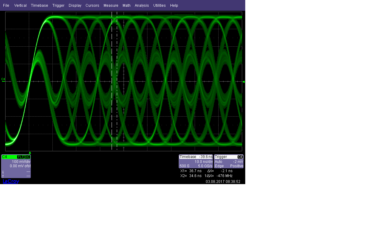
    This is the signl measured at the input of the 2412 with 100kHz input signal at Din2.

    I did some tests with OSC pin of the 2411 connected to a waveform generator to adjust different clocks. 
    After rising the clock over 6MHz the link started to work :-)
    But I don´t know why, is there something like aliasing or undersampling at 5MHz clock and 100kHz data at input?

    Regards

    Mario

  • Hi Mario,

    When devices in the BIST mode without applying any signal /frequency, do you see a high on PASS pin? Please follow 8.3.3 for testing BIST.

    Is there a reason why you apply a signal (100-200Khz) on Din2 ?

    Can you forward the system block diagram?

    I would suggest to check the following on the sytem ...

    Power supply noise
    LVCMOS inputs – overshoot, undershoot
    Quality of serial data eye
    Quality of input PCLK

    Regards,
    Dennis