Other Parts Discussed in Thread: DS125BR111, DS80PCI102
Hi,
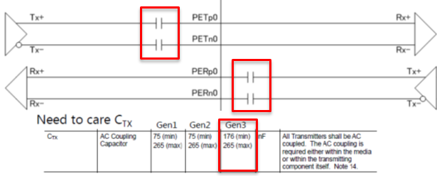
Let me talk about the PCIe Reference Schematic of SN75LVPE802.
The following circuit examples are described in the data sheet.
Please tell me the reason why the RX1P / N capacitor and RX2P / N have different capacities.
I would like to know why the value of the capacitor is different on host to device side.
I thought RX1P/N coupling capacitor should be 470nF.
Could you give me your advice.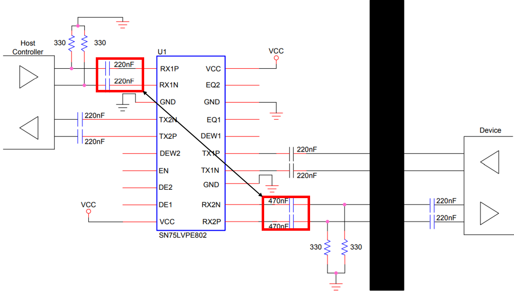
Best Regards,
Yusuke/Japan Disty