This thread has been locked.

If you have a related question, please click the "Ask a related question" button in the top right corner. The newly created question will be automatically linked to this question.

TPS2513A: Using the TPS2513EVM-527 evaluation module as a battery charger

Part Number: TPS2513A
Other Parts Discussed in Thread: TPS2513EVM-527, TPS2513, TPS2561A,

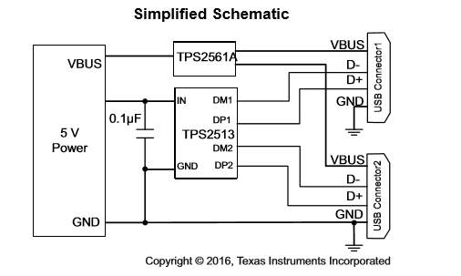
I am using the TPS2513EVM-527 evaluation module to try to charge the battery on the Samsung Galaxy S6 and S3, as well as the iPhone 6S. My input to the evaluation board is a 5 volt regulator that can source 40 mA. When I power up the board the LED's light up indicating proper operation. When I plug in any one of the phones to the demo board, the phone indicates that it is charging. The battery icon shows charging is active, but after several minute the charge percentage indicator drops by one percent. The phones think they are being charged but the  battery charging percentage is dropping. I am wondering if this reference board is suitable for charging these types of phones. Can anyone offer some support or guidance?

Thanks

  • Hello Frank,

    First, we are currently out of stock on our TPS2513 EMV's. I've ordered some more for me to work on, but they won't be in until next week so all the debugging I do until then will be looking through datasheets/user manuals and telling you what I think is occurring. I apologize for any inconveniences this may cause.

    1. Would you be able to send me a picture of your set up, or describe what jumpers you have connected on the EVM? I am mainly concerned with how you have the EVM currently configured.

    2. What is the current coming out of the usb port to the phone?

    3. Is there anyway that you can connect a different source that is able to supply more current? Curious to see if not enough current is being supplied to the phones to charge them. I know with some modern laptops, it will give a warning when a low power adapter is connected to the battery charger. Pretty much states that a charger has been detected but not enough current is being supplied to actually charge the laptop while in operation. This part is a DCP BC1.2 compliant part, so it has the ability to supply a maximum of 1.5A of current.

  • Hi Adam,
    Thanks for getting back to me. Here is what I have for my jumper configuration:
    I have removed J4 and J5. All other jumpers are installed on the board.
    I need to modify my USB cable to measure the current out of the USB port.
    Are you saying that the 5 volt 40 mA regulator (LT3525) is not good enough to drive the EVM?
    Unfortunately I have been in meetings all day. I'll get you a picture in a few hours.
    In the meantime, do you have an email I can send the picture to?
    Thanks so much Adam,
    Frank Hayden
  • Frank,

    "Are you saying that the 5 volt 40mA regulator (LT3525) is not good enough to drive the EVM?"

    Yes, my thinking is either that, or the 40mA is not enough to charge a phone. For example, if one of the phones require 60 mA to operate while the device is in use, and your only supplying the 40 mA, the phone will still detect that there is current coming into the phone so it will display the charging indicator but it's not enough to actually charge the phone. Typically, any USB port that you plug your phone in to charge, will supply at least 500mA of current, if not 900mA or 1.5A (depending on the port type)

    Below is a simplified schematic of how the EVM is designed. The device that is actually driving voltage and current to VBUS is the TPS2561A, not the TPS2513. Looking through the datasheet, I didn't see anything about a minimum current needed within the "recommended operating conditions" or "electrical characteristics" sections of the datasheet. However, what I did find within the description is the current limit threshold for this part which is 250mA to 2.8A. Since the 40mA that you are supplying is below this 250mA threshold, it may be causing some issues for the part to operate correctly.

    "I have removed J4 and J5. All other jumpers are installed on the board"

    Since these jumpers control VBUS, see what effect adding these jumpers has on the charging of the phones.

    "Do you have an email I can send the picture to"


    You can actually post pictures within this form. When you begin replying to the forum, you'll see an option at the bottom that says "Insert Code, Attach File, and more.." click that link and it will bring you to a separate page. From there click on the insert file icon, and you can insert a variety of different files including images.

    However, if you have information within the picture that you don't wish to include on a public forum, you are more than welcome to email me. Just click on my profile and my email should be in my bio.

    Let me know if any of this helps solve the problem.

  • Hi Adam,

    Thanks for the reply. I really appreciate it. I figured the 40 mA was not enough. Does TI have any 5 volt regulators that source 250 mA or more?

    Also if I try charging the phones with J4 and J5 installed does this not disable the TPS2561A? I'll try this and let you know what happens. Thanks for the suggestion.

    I took the picture of the test setup with my phone, so it is easier to email it to you. I will do that now. I will also update with my results from today.

    Thank you and best regards,

    Frank Hayden

  • Frank,

    "Does TI have any 5 volt regulators that source 250 mA or more?"

    You can actually use the TPS2561A as your current limiting device as it runs off of 5V as well. You will just have to change the resistor that's tied to the "ILIM" pin based on what current value you want the device to limit at. On the EVM, this is R7. To determine the resistor value based on the maximum current you want to allow, you will use the following equation and graph found on the data sheet. Depending on how accurate you want your current limit to be you can either solve the equation or eyeball the graph. For example, if you want the maximum current to be 500mA (which is usually the MINIMUM that phones charge at) you would use a 130k ohm resistor in place of R7.

    I believe this should fix your issue of charging the phones properly as you will now be able to source more current to the phones. If this does answer your question, please select this resolved my issue.

  • Hi Adam,

    Thanks again for all of your help. you have been outstanding in your responses.

    I will try and change the value Rilim so that the charging current is 500 mA. My one question is, if I do this will the regulator that drives the demo board be adequate at 5 volts and 40mA? If so, that is great news. I need to examine what Rilim I have know, and how changing it will help.

    Putting J4 and J5 bacl on the board disables the 2561A, so that does not work.

    I used a beefier supply to drive the board as sent to me by the factory, and was able to charge the phones today. Hopefully the resistor change will work with the current 5 volt regulator I have.

    Thanks and best regards,

    Frank Hayden
  • Frank,

    Are you asking if you can use the LT3525 regulator that has a supply of 40mA to drive the TPS2513A EVM? If that is what you are asking, that will not work as the EVM is still being supplied an inadequate current amount.
    What do you have plugged into the regulator? A DC power supply? You can just plug that straight into the TPS2513A EVM as long as it has a supply of 5V. There is no need for the external 40 mA current regulator as the TPS2561A on the EVM will be your current regulator.

  • Hi Adam,

    Thanks for your reply. That was what I was asking. I need to be a bit more explicit about my application.

    The system is an energy conversion project. Mechanical energy is converted to electrical energy. The conversion gives a voltage of anywhere from 2 to 4 volts. This voltage is then regulated to 5 volts and drives the EVM. That is why I need a 5V regulator, and why I was asking if TI offered a 5V regulator suitable for driving the EVM. On Friday I was able drive the EVM with a good 5V power supply and the device charges the phone at a rate of about 1% every seven minutes. I need to complete the next step which is drive the board with the conversion design. I can't do that until I get a suitable 5V regulator that will step up the conversion voltage to a regulated 5V and drive the EVM. I hope this makes more sense, and explains why I need a regulator. Do you have any thoughts?

    As always, thanks so much for your prompt and courteous replies.

    Best regards,

    Frank Hayden

  • Frank,

    I see. In that case, I would close this thread and open another one within the power management integrated source group (PMIC)

    https://e2e.ti.com/support/power_management/pmu

    They can help you pick a regulator needed for this project better than I can as they have engineers assigned to those specific products. Just explain to them the end application like you just did to me, but also add in how it needs to be able to supply at least 250 mA of current, with 500 mA or more being ideal. If you are able to find a proper regulator with the ability to handle that current, your application should work.

    Best of luck with your project, and if this thread helped you, please click  This resolved my issue

  • Thanks Adam,

    You have been very helpful.

    Best regards,

    Frank Hayden