This thread has been locked.

If you have a related question, please click the "Ask a related question" button in the top right corner. The newly created question will be automatically linked to this question.

TPS65981: USB-PD able to send data on USB_RP D+ but not USB_RP D-

Part Number: TPS65981

Hello,

I am working with a customer who is have trouble getting data out of the TPS65981 USB 2.0 MUX.

They are able to pass the D+ signal out of the USB_RP port to their SoM, but when the D- signal is connected the signal goes to 0 V.

When the RP port is not connected to the SoM, the USB_RP pins show D+ and D- working fine.

When the TPS65981 is bypassed completely, and the USB port is connected to the SoM, the USB works fine. 

Both the D+ and D- pin going to the SoM ohms out at 200Kohms w/ respect to ground, the resistance on the USB-PD measures open.

Do you have any ideas as to what could be causing this behavior?

  • Hi Jon,

    Can you send me a schematic that I can look at to see how your customer is implementing the TPS65981 and the MUX?
  • Hi Adam,

    Per our previous discussions the customer is in fact using the TPS65986.

    I have a follow up question: does the USB bus get passed through the USB MUX only when the USB RP ENABLE option in the Application Customization Tool is selected?

    It looks like on page 23 in this guide:

    There is a section called USBPath that shows whether USB RP and EP will be enabled.

    In the 00 case where RP and EP are disabled, how does the USB Mux behave?

    Thank you,

    Jon

  • Hi Jon,

    To make it easier for me, I'm going to reply to both your questions here.

    Question 1: Problem with D+/D- lines

    I was look thing through the schematic you sent me, and there are a few things that I noticed.

    -  You are using two separate protection devices. L86/L87 and U60. There is no need to have both within the system as they achieve the same thing. What I would recommend doing is depopulating L86/L87, short the lines together, and see if that fixes the issue.

    - Make sure the stub trace for the U60 and the connections to both D+/D- lines are as short as possible.

    Question 2: USB MUX RP enable

    There are a few factors that play into whether data passes through the USB MUX, and enabling Rp is one of them. To ensure that the USB liens pass through regardless of outside factors, Enable Rp, Disable Ep, and Disable Billboard

    Let me know if this answers your question or not! If so, please click This resolved me issue

  • Hi Adam,

    The customer has found that when he places a 220 - 300 Ohm resistor on the D- line between the SOM and the USB-PD chip I do get a signal on the D- line. Is there any way to increase the drive strength of the USB_RP_N signal? Under normal circumstances should this series resistance be required?

    Thank you,
    Jon
  • Hi Jon,

    You typically do not want to put any resistance on the D+/D- lines as you can have a voltage drop across that resistor, which causes an issue with data and BC1.2 detection. I believe that the issue is due to L86/L87 and a potential large stub for the connection to U60.

    You cannot increase the drive strength of the USB_RP_N signal.

    Let me know if this helps or not!
  • Hi Adam,

    The customer tested with L86/L87 shorted with 0 ohm resistors and saw no change in functionality.

    We are now thinking that the Host/Device negotiation might not be occurring properly. How does the USB-PD controller negotiate USB-OTG with regard to who is the host and who is the device? 

    Thank you for your help,

    Jon

  • Hi Jon,

    That could be the issue.

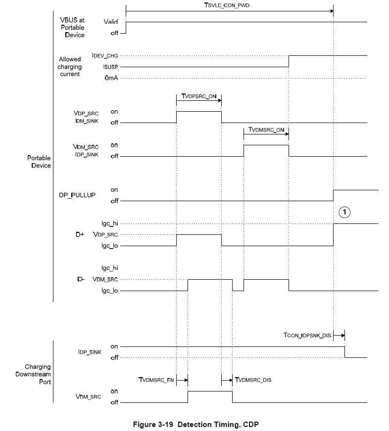
    I’ll give an example for if you are trying to test and verify for Charging Downstream Port (CDP mode).  Here's a CDP timing diagram example found within the BC1.2 specification. The portable device starts the conversation by sending a signal on the shared D+ line.  The source device detects this, and sends a response back on the D- line. The Portable device receives this response, and to verify that the D+ and D- lines are not shorted together (DCP mode), it sends another signal back through the D- line. The source device receives this signal through the D- line, but does not send back a response. Since the portable device never received a signal back on the D+ line, it knows that the D+ and D- lines are not shorted together, thus it is in CDP mode.

    Let me know if this helps or not!

  • Hi Jon,

    I am closing this thread since I have not heard from you in a while. If you feel like I was able to help answer your question, please click This resolved my issue!

    If not, feel free to reply to this thread or start a new one