

Other Parts Discussed in Thread: TINA-TI, , , DS90LV012A
Tool/software: TINA-TI or Spice Models
I was trying to use the DS90LT012A receiver IBIS model along with the DS90LT011A driver and was getting crazy results i.e. many reflections due to impedance mismatch
Having looked at the IBIS file it seems to me that the 100Ω termination resistor has not been included in the data for the Power clamp and ground clamp I-V curves.
For example looking at the Power Clamp Vcc relative of the DS90LT012A IN+ pin gives the following curve, which I believe is modelled without the internal 100Ω termination resistor. (see below)

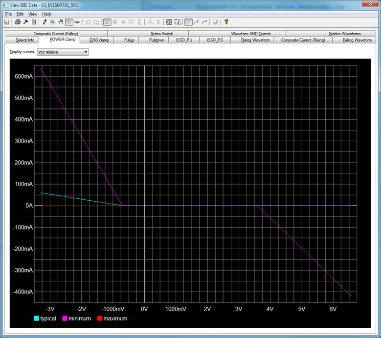
However looking at an IDT ICS8S89876I receiver IN pin gives a very different set of curves, which are what I would expect. (see below)
Adding a 100Ω termination resistor to the simulation sorts thee problem out for me, which I take as proof that the simulation IBIS model is incorrect.
Can you please provide an updated IBIS model for the DS90LV012A part? Or better still a model over the full temperature range of the DS90LT012AQ-Q1 part?
Regards,
David
