This thread has been locked.

If you have a related question, please click the "Ask a related question" button in the top right corner. The newly created question will be automatically linked to this question.

TIOS101: TIOS101-3 failed short circuit test

Part Number: TIOS101

hi,

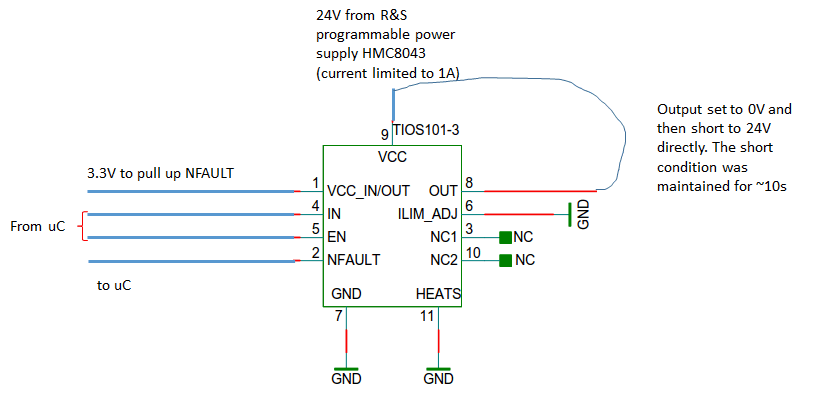
One of my customer is dong short circuit test for TIOS101-3 using the below process and found device damaged. Any clue or advice how to cure? 

1. Drive output low --> uC controls the input of TIOS101-3. --> Voltage 3.3V
2. Short output with 24V
3. Keep the short condition continuously for more than 5-10 sec. (FAULT pin shows an error according to the datasheet --> Expected behavior.).
4. remove short
5. Observe if damaged --> Output stage damaged. Output impedance is 130 Ohm after measurement --> Unexpected behavior

After step 5, the IC is continuously in short circuit mode because output stage is damaged.
I did the test on two chips on my PCB and unfortunately both are damaged.
I_LIM_ADJ pin is shorted to Ground.

Thx in advance.

Best regards,

kpk

  • Hi KPK,

    I repeated this same test on an EVM here and was unable to reproduce the failure. I only had one unit available, so I have ordered a few more to support additional tests.

    In general the device should be protected from these kinds of overcurrent conditions via two mechanisms: the output current monitoring (and automatic shut-off) as well as thermal shutdown. These should help reduce the likelihood of this kind of failure.

    Can you please explain a little more how the short circuit is applied? If the short occurs through a cable, then there is a chance that voltage spikes could occur due to the way the inductance of the cabling responds to a fast change in current (which would occur, for example, when the TIOS101 driver shuts off). If you had oscilloscope probes capable of supporting higher voltages, you could check for these kind of transients by monitoring the OUT pin and 24-V supply while the short is applied.

    I'm also curious about the power supply used. This condition results in a large and relatively quick change in load current. Some power supplies may respond to load transients with overshoots or ringing on their regulated output. This could again be checked via an oscilloscope.

    Regards,
    Max
  • hi Max,

    Below is the information: 

    I_LIM_ADJ pin is shorted to Ground.  This means Rset is zero

    The short was done using a simple cable. No load on 'out' pin during the short.

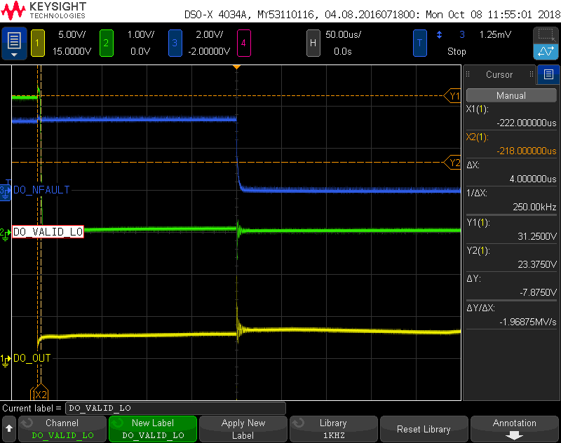
    To give you some more insight of the testing, below is the oscilloscope measurement during the short.


    DO_NFAULT = NFAULT signal from IC (pin 2)
    DO_Valid_LO = it is a signal that monitors the output voltage (this is our internal requirement). The monitoring is using simple transistor based solution. Goes low if the output is HIGH.
    DO_OUT = output (pin 8) of the IC,

    I agree that there was overshoot and ringing observed during the measurements. But this was observed when FAULT signal went low.

    Kindly check and let me know if you can draw some conclusion out of it.

    Best Rgds,

    kpk

  • KPK,

    I should get the new units tomorrow, so I can check a few more parts then.

    In the meantime, I'd be interested in understanding the overshoots a little better. The ringing on DOUT shown in your screenshot corresponds to when the output driver shuts off (as signaled via a falling edge on NFAULT), so it likely due to current rapidly changing across a cable inductance. There may be a similar phenomenon as well when the current switches back on (~15 ms later). Do you think you could check both of these conditions and zoom in a bit more on the oscilloscope's horizontal scale so that we can see the full amplitude of the ringing?

    My concern is that the overshoots are damaging the part, either directly due to over-voltage stress or by triggering the internal transient protection clamping circuits (which would then try to sink current from your DC rail and become damaged). If this were the case, then a solution as simple as some additional capacitance on the OUT pin may help.

    Max
  • hi Max,

    My PCB are limited sets and I cant afford to damage anymore of them. Hence I will not be doing any more short circuit test until I have IC samples which already requested. I should be to test it next week once i get the sample to replace.

    at the mean time, can you run just one test for me?

    1. Keep the output in tristate and short to zero. (EN pin is low or open)
    2. Same as 1 but short to 24V

    Best regards,
    kpk
  • KPK,

    I tried this test and did not notice any unexpected behavior. With the EN pin tied low, the output of the device acted as a high impedance whether 0 V or 24 V was applied. Neither condition seemed to damage the device.

    I also repeated the previous testing of shorting OUT to VCC (set to 24 V) with RSET = 0 Ohms, EN high, and TXD high (so that OUT is pulled low) across three different EVMs. I saw the correct behavior from all of them. The driver recognized an overcurrent condition and shut off automatically, and then retried on a periodic basis. When the driver was enabled it would pull the OUT line down by 5-10 V (not all the way to 0 V since my power supply is stronger than the TIOS driver). Upon automatic disable of the driver, I did not observe any overshoots as the output voltage increased back to 24 V. (My shorting wire was relatively short - about 0.5 m).

    Regards,
    Max
  • KPK,

    I was just curious if you had any further progress on resolving this. Have you received the replacement samples and conducted the testing you had planned?

    Thanks,
    Max
  • hi Max

    Thx for follow up:

    Yes. just got the sample IC to test on the board. Looks fine for us. It indeed looks like the damaged IC was one isolated incident and hence can be ignored at present.

    Can I check are there any inherent differences between high and low side drivers? In other words, if I set maximum output current to 200mA then what value should I expect for high side driver output and low side driver output? Maximum variations in % or absolute value are ok. I am sure TI should have the data (either graphical or tabular format) over the entire range
    I would like to know the differences because this could be a safety critical issue from our design point of view. We design based on IEC 61508 standard. We need this information for our design parameters.

    Best regards,

    KPK

  • KPK,

    The output current is not continuously limited, the RLIM resistance is just used to set the threshold value for over-current warning/shut-off. So, the instantaneous current flowing in a short-circuit condition would be limited only by the short resistance, the output impedance of the high-side or low-side drivers (which is about 4 Ohms in both cases), and the impedance of the power supply (VCC and ground return). Currents above the configured limit value that persist for longer than the current fault blanking time result in fault indication and shut-off.

    Max