This thread has been locked.

If you have a related question, please click the "Ask a related question" button in the top right corner. The newly created question will be automatically linked to this question.

TUSB1064: TUSB1064RNQEVM unable to display monitor(use the type-C Cable)

Part Number: TUSB1064

Hi, support team

We tested a EVM board(TUSB1064RNQEVM) using the Notebook two Type-C port(support Displayport both)

1st Type-C port was fine( EDID/Screen).

2nd Type-C port is fail(EDID OK, but no display to monitor) .

Check the 2nd Type-C port  we found the HPD signal was unstable(high-> low-> high ->low....).

I thought the signal of 2nd Type-C port is weak.(DP link fail ?!)

What do we find the display issue?

Display_issue.pdf

  • Pei

    How long is the duration when HPD is low? If HPD is low for ~1ms, then it is a HPD_IRQ which could mean link training failed with 2nd Type-C port. If HPD low for min of 3ms, then this is disconnect.

    You can force HPD to be high by populating resistor R82 on the EVM. But I think we need to distinguish HPD between HPD_IRQ and HPD disconnect.

    Thanks
    David
  • Hi, David

    Thanks for your reply,

    The HPD signal(2nd Type-C port) of EVM board are pic1& pic2. Look likes link training failure.

    Pic1:HPD signal

    Pic2  (Scope Zoom in): HPD(Low) <1mS

    Our EVM board schematic is attached file(R82 is 0ohm between VBUS and SYS_PWR).  

    1513.HSDC025A-002_UserGuide.docx

  • Pei

    Please use a multimeter to check AUXp and AUXn voltage, AUXp voltage needs to be between 0 to 0.4V while AUXn voltage needs to be between 2.7 and 3.6V.

    If AUX voltage is correct, please probe DP0, DP1, DP2, and DP3. Are you doing 2 lane or 4 lane DP?

    If you are seeing signals, you may need to adjust the DPEQ values to compensate the channel loss.

    Thanks
    David
  • Hi, David

    Are you doing 2 lane or 4 lane DP?

    =>EVM is set 2 lane DP .

    If you are seeing signals, you may need to adjust the DPEQ values to compensate the channel loss.

    => Yes, I already changed the DPEQ setting (Low / R / F / High),but issue not solved.

    Yesterday, we monitor the AuxN& AuxP signals and found the something error that the log showing 5.4Gbps , 2.6Gbps and 1.62G link fail.

    I want to know what I should do next ???

    Pei

  • Pei

    Would you please share the log file with me?

    Thanks
    David
  • Hi David

    Link training failure log from Aux channel.

    Password:123

    PeiCOM7_AuxLog_Summary.7z

  • Pei

    I see the request of changing voltage swing and pre-emphasis being made in the log file, but I do not see the lane status after the request is being made.

    One thing I do see is that the max lane count is 4. This is not correct. Host needs to set its max lane count to 2 so the sink will set its max lane count to 2 as well. If host and sink both set max lane count to 4 and send the data on all 4 lanes, but TUSB1064 is only supporting 2 lanes, sink will never see the data on 2 of the 4 lanes since these 2 lanes are disabled by TUSB1064. You can also set sink max lane count to 2 and this will force the host to change the lane count to 2 as well.

    Thanks
    David
  • Hi, David

    A question:   TUSB1064 is only supporting Displayport 2 lanes ?? 

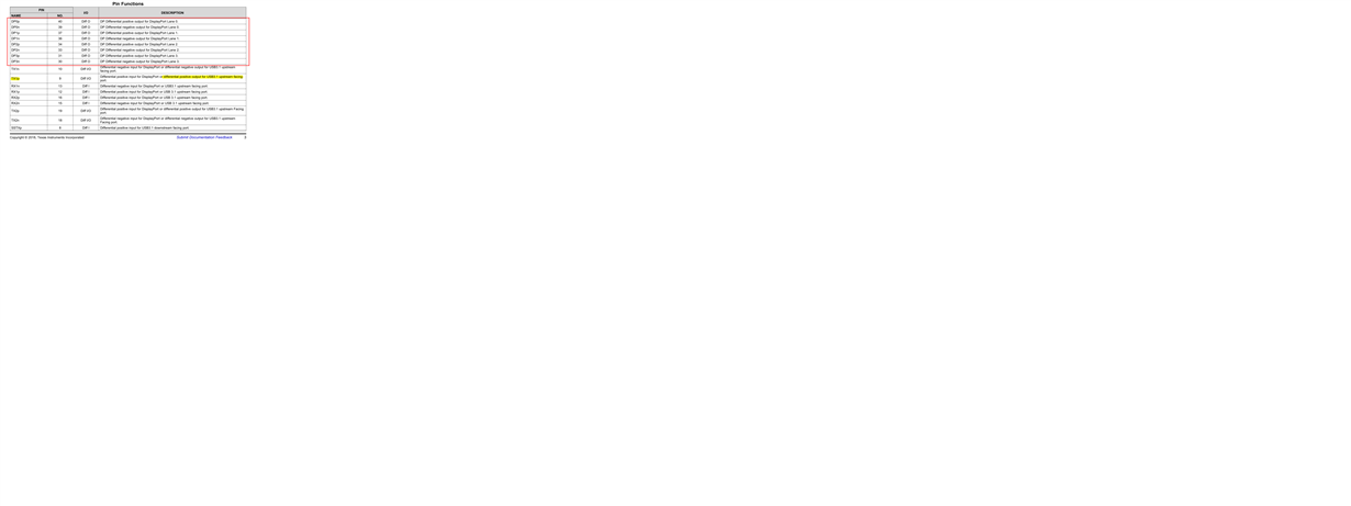
    The TUSB1064 pin functions of datasheet as below pic:

    look like to support Displayport 4lanes.

  • Pei

    TUSB1064 supports 2 DP lanes or 4 DP lanes as configured by the CTL0 and CTL1 pins, which in turn are driven by the PD controller.

    The overall communication/configuration is this

    1. Host and TUSB1064 PD controller communicate across CC1/CC2. If TUSB1064 PD controller has its multi-function bit set, then it will configure TUSB1064 as USB+2 DP lanes. If multi-function bit is not set, then it will configure TUSB1064 as 4 DP lanes. The host PD controller also needs to configure DP source to be 2 lanes or 4 lanes depending on the CC1/CC2 communication.

    2. DP source and DP sink then communicates the max lane count through the AUX channel, the max lane count can be supported is 2. In case it would be DP source (2 lane) --- TUSB1064 (2 lane) --- DP sink (2 lane).

    If host controller does not change DP source lane count, then it will always set to 4. You would have the scenario of DP source (4 lane) --- TUSB1064 (2 lane) --- DP sink (4 lane). Link training will not work since 2 lanes are disabled by TUSB1064. And this is what I saw from the AUX log file.

    You can disable multi-function bit and re-program the TUSB1064 controller. In this case, it will be DP source (4 lane) --- TUSB1064 (4 lane) --- DP sink (4 lane). Or you can still set multi-function bit but change DP sink to be 2 lane, then it will be DP source (2 lane) --- TUSB1064 (2 lane) --- DP sink (2 lane).

    Thanks

    David

  • Hi, David

    Thanks for your suggestions, i will discussion with the monitor vendor (or IC vendor). 

    To check the multi-function bit of sink side(set to be 2 lane).

    In addition,in your experience

       1. How about the TUSB1064 EVM compability?(monitor)

       2. TUSB1064 set to I2C mode better than GPIO mode? 

    Thanks.

    Pei  

  • Pei

    TUSB1064 EVM is compliant to the DP spec, it will work with DP compliant monitor.

    I2C mode is the same as GPIO mode, except it gives individual equalizer control for each lane while GPIO mode does not.

    Thanks
    David