This thread has been locked.

If you have a related question, please click the "Ask a related question" button in the top right corner. The newly created question will be automatically linked to this question.

SN65DSI83-Q1: Does Not Show Test Pattern

Part Number: SN65DSI83-Q1
Other Parts Discussed in Thread: DSI-TUNER, SN65DSI83

Hi,

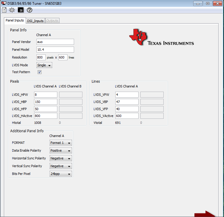
         we are using SN65DSI83-Q1, i have interfaced with LVDS panel configured through the I2C, following value are write in registers

i2cWriteByte(i2c_fd,0x09,0x00);        //software reset
        usleep(10000);
        i2cWriteByte(i2c_fd,0x0D,0x00);        //PLL register disable mode
        usleep(10000);
        i2cWriteByte(i2c_fd,0x0A,0x03);        //set lvds clock range    //don't change this    
        usleep(10000);
        i2cWriteByte(i2c_fd,0x0B,0x40);        //dsi clock divider    //
        usleep(10000);
        i2cWriteByte(i2c_fd,0x10,0x00);        //Lane configuration
        usleep(10000);
        i2cWriteByte(i2c_fd,0x11,0x00);        //equalization
        usleep(10000);        
        i2cWriteByte(i2c_fd,0x12,0x30);        //DSI clock range
        usleep(10000);        
        i2cWriteByte(i2c_fd,0x18,0xE8);//7A        //data bit format
        usleep(10000);
        i2cWriteByte(i2c_fd,0x19,0x02);        //control the differential voltage
        usleep(10000);    
        i2cWriteByte(i2c_fd,0x1A,0x02);        //lvds differential termination
        usleep(10000);
        i2cWriteByte(i2c_fd,0x1B,0x10);        //commmon mode voltage
        usleep(10000);
        i2cWriteByte(i2c_fd,0x20,0x20);        //horizontal length low
        usleep(10000);
        i2cWriteByte(i2c_fd,0x21,0x03);        //horizontal length High
        usleep(10000);
        i2cWriteByte(i2c_fd,0x24,0x58);        //vertical display low3    
        usleep(10000);
        i2cWriteByte(i2c_fd,0x25,0x02);        //vertical display High
        usleep(10000);
        i2cWriteByte(i2c_fd,0x28,0x9c);        //sync delay low
        usleep(10000);
        i2cWriteByte(i2c_fd,0x29,0x07);        //sync delay High
        usleep(10000);
        i2cWriteByte(i2c_fd,0x2C,0x08);        //Hsync Pulse width low
        i2cWriteByte(i2c_fd,0x2D,0x00);        //Hsync Pulse width High
        i2cWriteByte(i2c_fd,0x30,0x04);        //Vsync Pulse width low
        i2cWriteByte(i2c_fd,0x31,0x00);        //Vsync Pulse width High
        i2cWriteByte(i2c_fd,0x34,0x96);        //HORIZONTAL_BACK_PORCH
        i2cWriteByte(i2c_fd,0x36,0x2F);        //VERTICAL_BACK_PORCH
        i2cWriteByte(i2c_fd,0x38,0x32);        //HORIZONTAL_FRONT_PORCH
        i2cWriteByte(i2c_fd,0x3A,0x28);        //HORIZONTAL_FRONT_PORCH
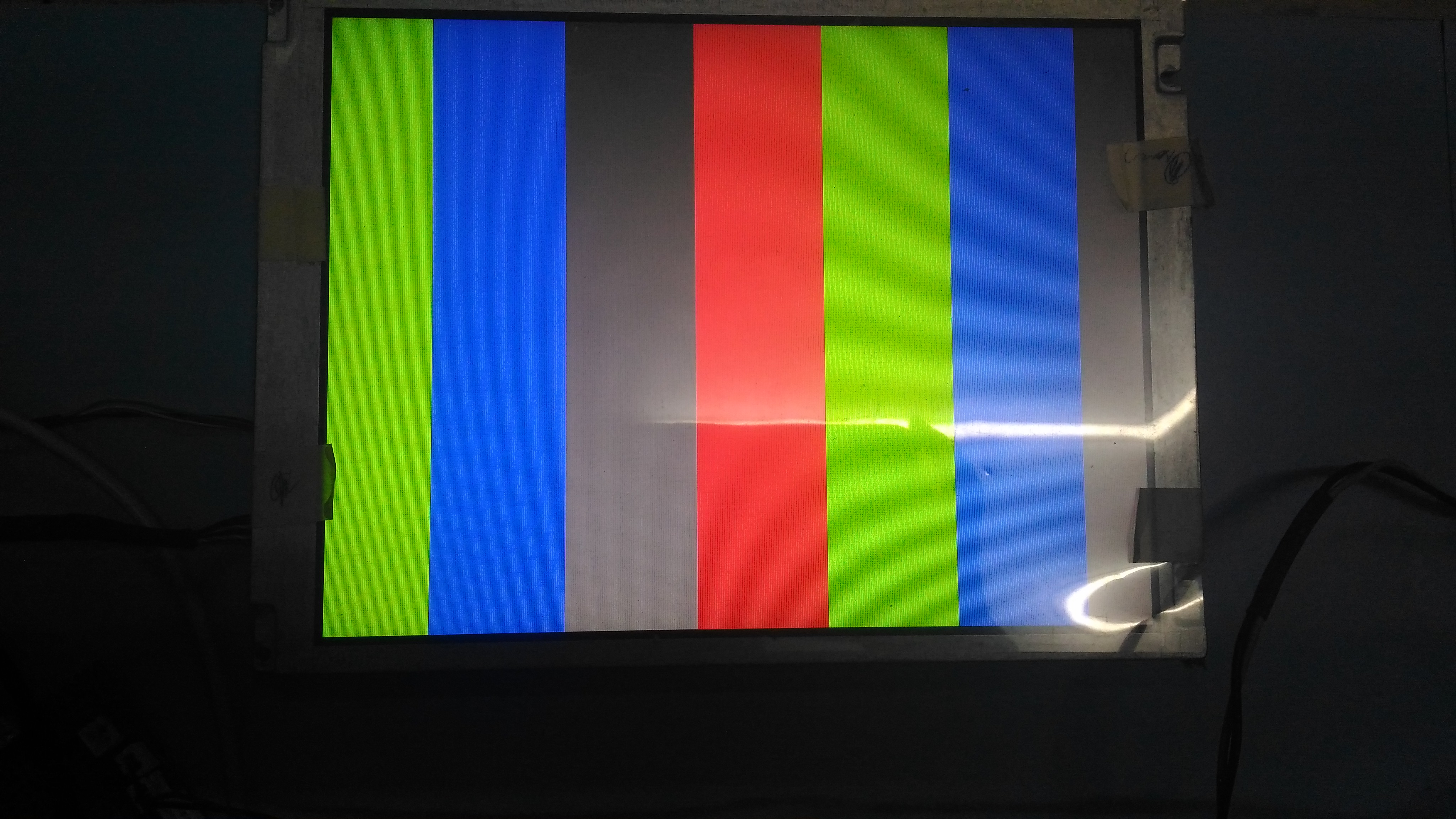
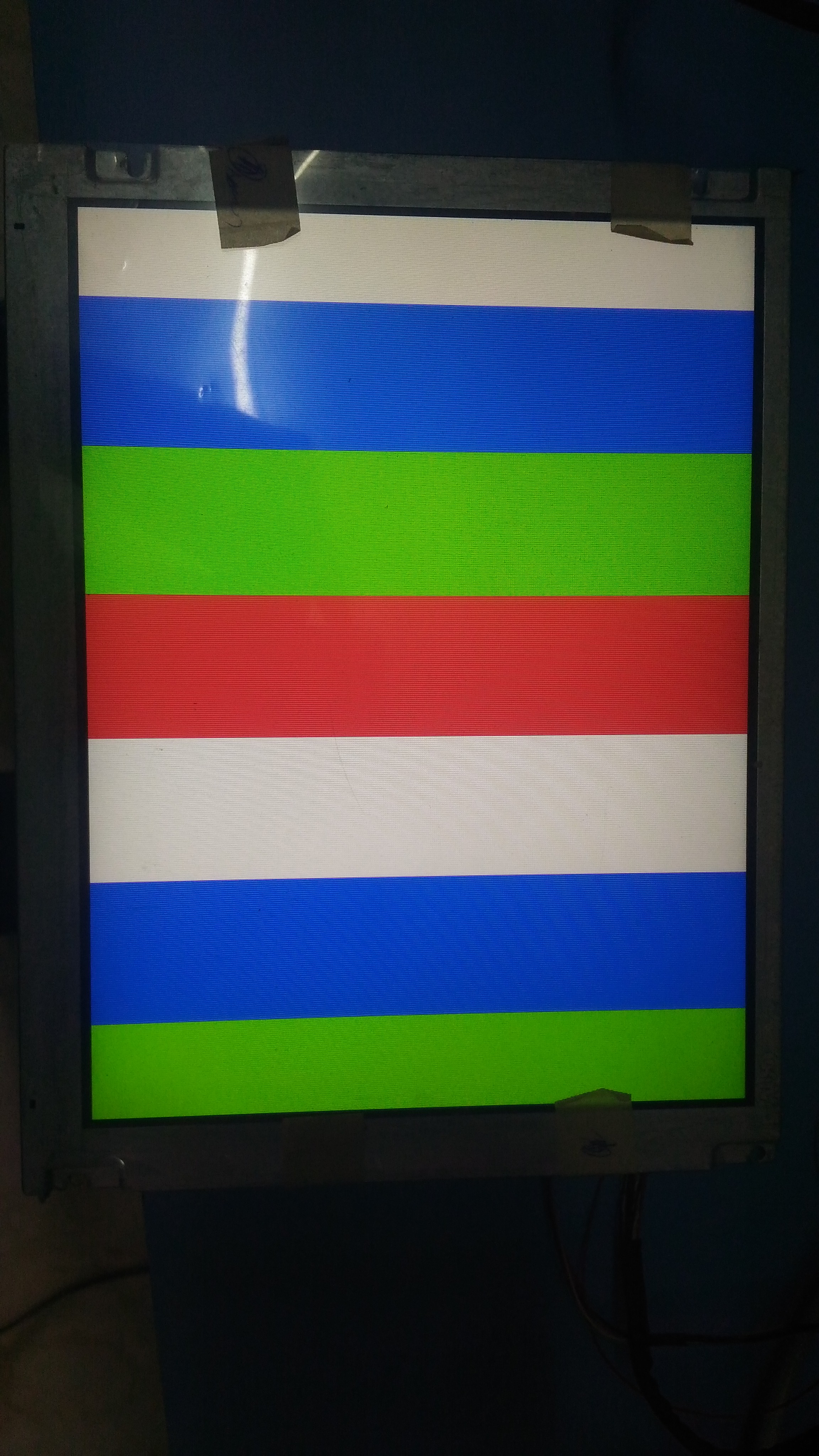
        i2cWriteByte(i2c_fd,0x3C,0x10);        //Test Pattern Enable
        usleep(10000);                        //10 ms delay
        i2cWriteByte(i2c_fd,0x0D,0x01);        // enable the PLL    
        usleep(10000);                        //10 ms delay
        i2cWriteByte(i2c_fd,0x09,0x01);        // software reset    
        usleep(10000);                        //10 ms delay
        printf("writing completed....\n");   

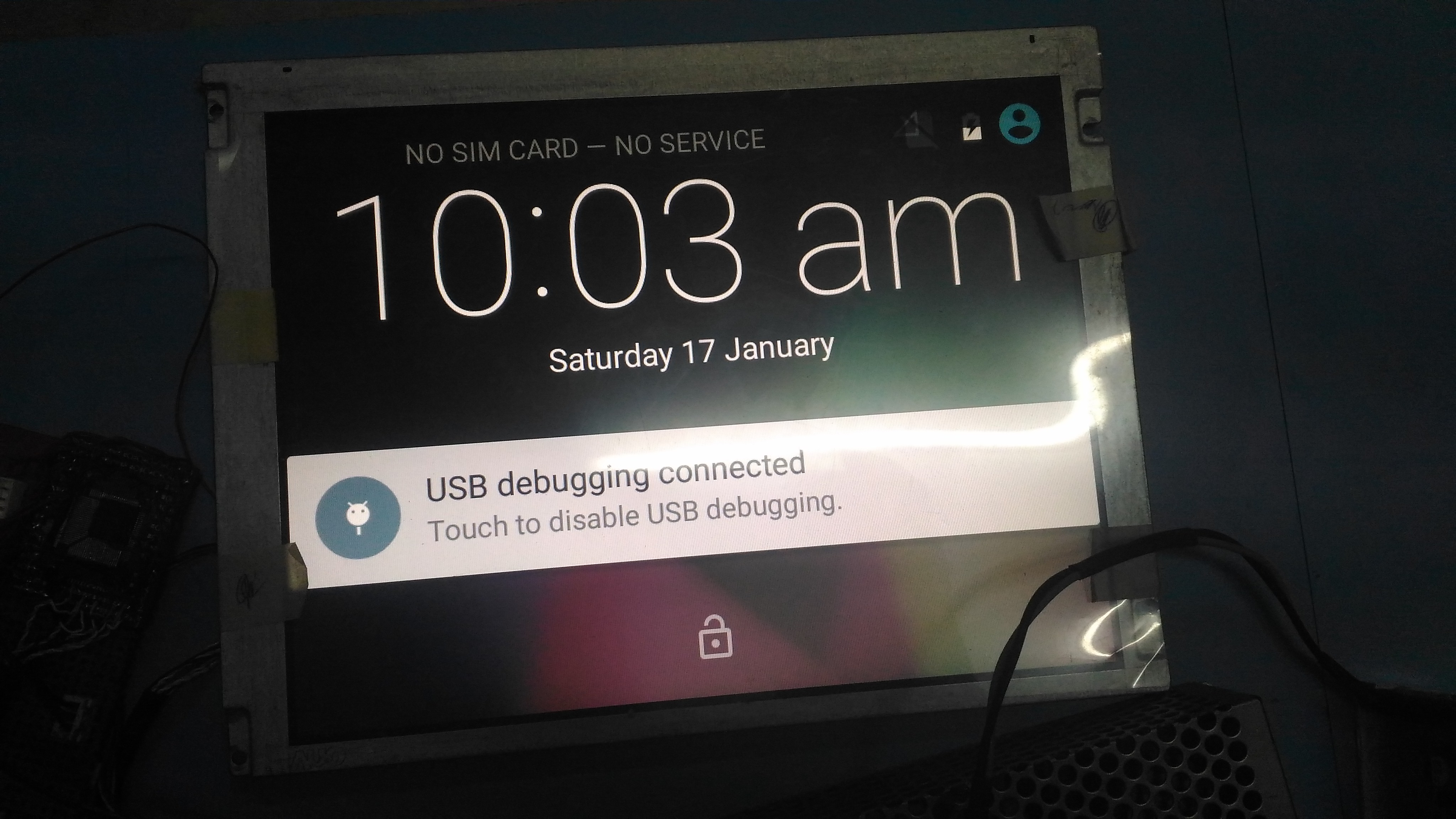
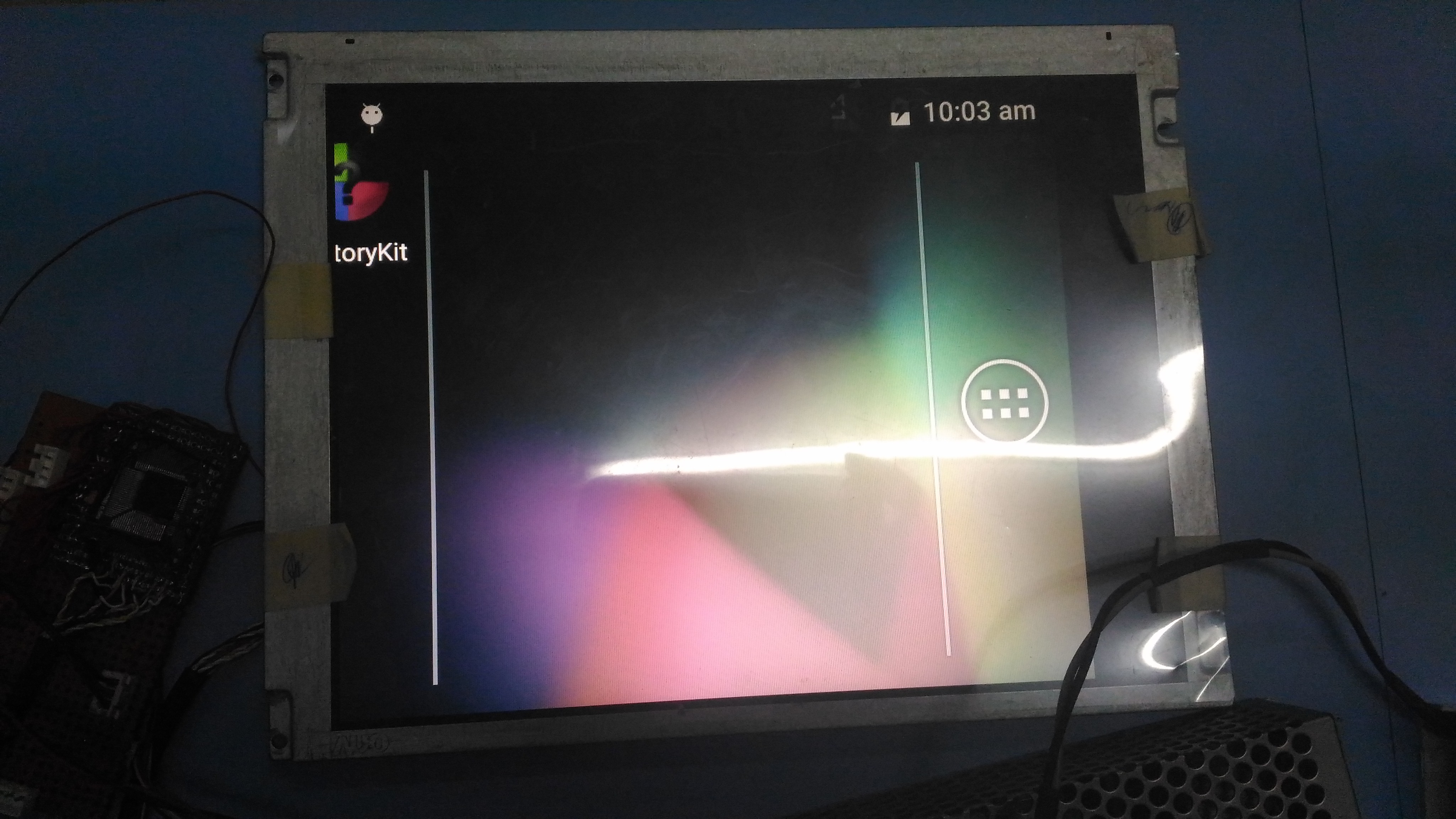
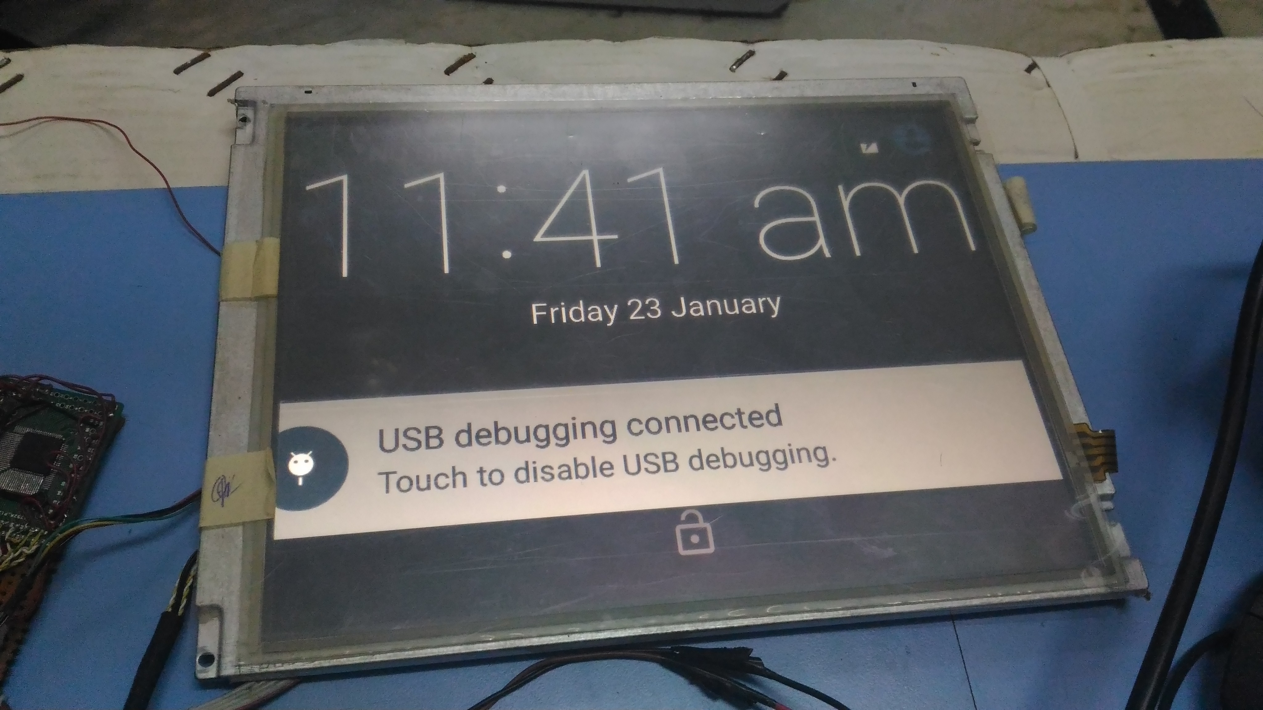
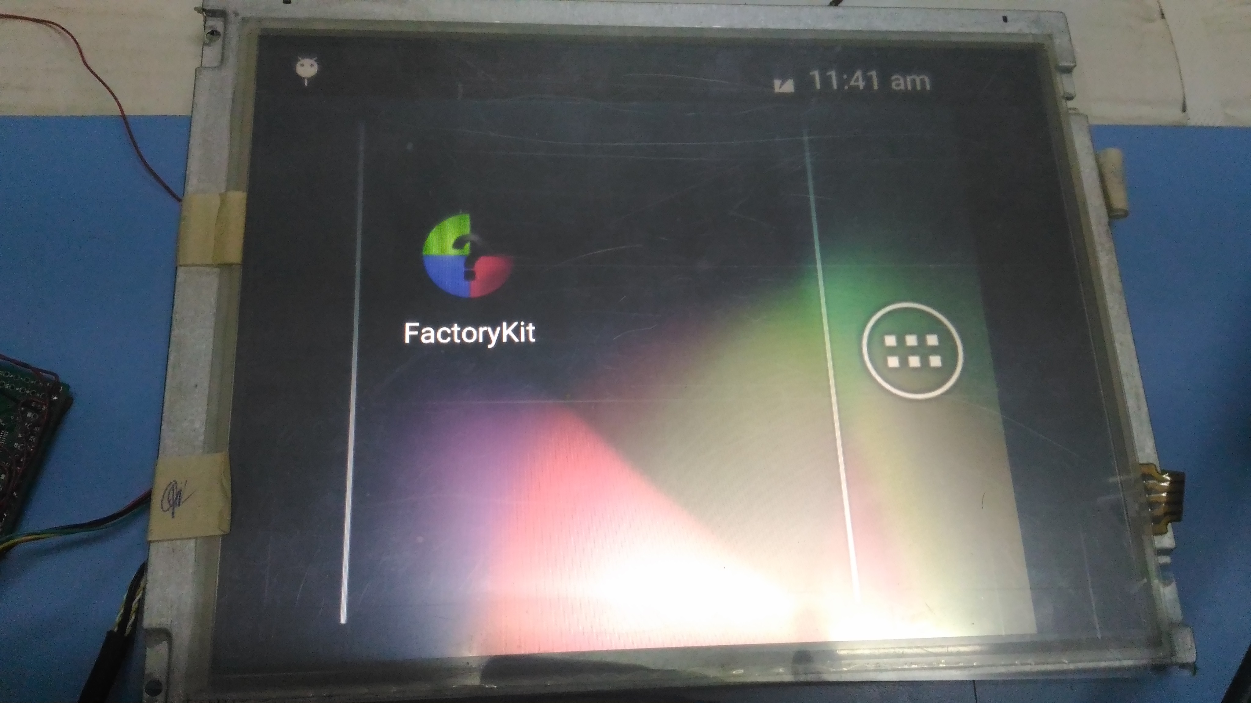
        After write these values panel did not show the test pattern. i didn't give any DSI signal and clock to the SN65DSI83-Q1. If i made any mistake please correct me, my panel data sheet attached here.

Thank you....up-02-123.pdf

  • Hi babu,

    You still need to supply a clock if you want to use the test pattern.

    Please also use the DSI-Tuner to configure the register settings. You can reference this video as an example: www.youtube.com/watch, and you would just need to check the "Test Pattern" box in the tool.

    Regards,
    I.K.
  • Hi sir,
    Thanks for your reply, Test pattern is shown(only particular area in display) but my display get flickering. i want more clarification ,
    1. Test pattern also need correct Initialization Sequence?
    2. when i read the E5 register PLL unlock state, this create any problem in test pattern?

    My dtsi file is,

    &mdss_mdp {
        dsi_auo_video: qcom,mdss_dsi_auo_video {
            qcom,mdss-dsi-panel-name = "auo video mode dsi panel";
            qcom,mdss-dsi-panel-controller = <&mdss_dsi0>;    
            qcom,mdss-dsi-panel-type = "dsi_video_mode";
            qcom,mdss-dsi-panel-destination = "display_1";
            qcom,mdss-dsi-panel-framerate = <57>;
            qcom,mdss-dsi-virtual-channel-id = <0>;
            qcom,mdss-dsi-stream = <0>;
            qcom,mdss-dsi-panel-width = <800>;
            qcom,mdss-dsi-panel-height = <600>;
            qcom,mdss-dsi-h-front-porch = <50>;
            qcom,mdss-dsi-h-back-porch = <150>;
            qcom,mdss-dsi-h-pulse-width = <8>;
            qcom,mdss-dsi-h-sync-skew = <0>;
            qcom,mdss-dsi-v-back-porch = <47>;
            qcom,mdss-dsi-v-front-porch = <40>;
            qcom,mdss-dsi-v-pulse-width = <4>;
            qcom,mdss-dsi-h-left-border = <0>;
            qcom,mdss-dsi-h-right-border = <0>;
            qcom,mdss-dsi-v-top-border = <0>;
            qcom,mdss-dsi-v-bottom-border = <0>;
            qcom,mdss-dsi-bpp = <24>;
            qcom,mdss-dsi-color-order = "rgb_swap_rgb";
            qcom,mdss-dsi-underflow-color = <0xff>;
            qcom,mdss-dsi-border-color = <0>;
            qcom,mdss-dsi-on-command  = [00 00 00 00 00 00 00];
            qcom,mdss-dsi-off-command = [00 00 00 00 00 00 00];
            qcom,mdss-dsi-on-command-state = "dsi_lp_mode";
            qcom,mdss-dsi-off-command-state = "dsi_hs_mode";
            qcom,mdss-dsi-h-sync-pulse = <1>;
            qcom,mdss-dsi-traffic-mode = "burst_mode";
            //qcom,mdss-dsi-traffic-mode = "non_burst_sync_pulse";
            qcom,mdss-dsi-lane-map = "lane_map_0123";
            qcom,mdss-dsi-bllp-eof-power-mode;
            qcom,mdss-dsi-bllp-power-mode;
            qcom,mdss-dsi-lane-0-state;
            qcom,mdss-dsi-lane-1-state;
            qcom,mdss-dsi-lane-2-state;
            qcom,mdss-dsi-lane-3-state;
            qcom,mdss-dsi-panel-timings = [F5 0E 0A 01 2E 32 0E 12 0D 03 04 00];
            qcom,mdss-dsi-t-clk-post = <0x5>;
            qcom,mdss-dsi-t-clk-pre = <0x24>;
            qcom,mdss-dsi-bl-min-level = <1>;
            qcom,mdss-dsi-bl-max-level = <4095>;
            qcom,mdss-dsi-dma-trigger = "trigger_sw";
            qcom,mdss-dsi-mdp-trigger = "none";
            qcom,mdss-dsi-bl-pmic-control-type = "bl_ctrl_wled";
            qcom,mdss-dsi-reset-sequence = <1 20>, <0 2>, <1 20>;
            qcom,mdss-dsi-force-clock-lane-hs;
        };
    };

    I am running DSI CLK lanes in HS state, i didn't connect any DSI data lane to SN65DSI8x.

    Thank you..

  • Hi babu,

    Yes, the relevant sections of the initialization sequence still need to be followed for the test pattern. You should also clear register 0xE5 before reading from it as some bits may get erroneously set during the initialization sequence.

    Please use the DSI-Tuner tool to configure the registers and post screenshots of each tab so that I can check your settings.

    And please also post picture of your display so that I can see what you mean by only a particular area being displayed.

    Regards,
    I.K.
  • Hi I.K. Anyiam sir,

    my previous problems are solved now test pattern shown correct. but still the PLL didn't lock here before i read the E5 register i have clear that register by writing 0xFF to that. 

    here i attached DSI Tuner screenshots.

    Thank you...

  • Hi babu,

    That test pattern does not look correct. It should look like this:

    Please share your schematic with me at i-anyiam@ti.com. I suspect you may be using the wrong mapping format.

    Regards,

    I.K. 

  • Hi babu,

    Please try using the attached .dsi file and txt file for the register configuration:

    /cfs-file/__key/communityserver-discussions-components-files/138/babu.dsi

    /cfs-file/__key/communityserver-discussions-components-files/138/babu.txt

    You can import the .dsi file into the DSI-Tuner tool to see the settings I used.

    Note that it is configured for Format 2 like the panel datasheet is expecting, so you should also ensure that A_YOP/N is connected to RxIN0, A_Y1P/N is connected to RxIN1, A_Y2P/N is connected to RxIN2, and A_Y3P/N is connected to RxIN3 on the panel. You also need 8 bit mode selected for the panel. 

    Also ensure that the processor is outputting the same DSI parameters entered in the above .dsi file.

    Regards,

    I.K. 

  • Hi I.K. Anyiam sir,

    Now i am getting test pattern following format still any error is present or not?

    Still PLL not locked after reading the E5 register i am  getting 0x01 value,

    After test pattern completed,i have configured the registers as per above method, after i given all the data line to SN65DSI83 but i getting white screen.

    i have one more clarification, Dsi tuner is suggested 120 Mhz but my host processor produced 270 Mhz so i have reconfigured the registers as per my host frequency, is this creating any problem.

    Thank you...

  • Hi babu,

    Yes, this would cause issues. Right now the divisor value for the DSICLK is 3, which would result in 40MHz LVDS clock when the DSICLK is 120MHz. If the DSICLK is actually 270MHz, then the LVDSCLK would be 90MHz, which is out of specification of your display datasheet. If you want to use 270MHz then you need to change the divisor value to 6, but then this would result in a line time mismatch between the DSI side and the LVDS side so you would need to insert more blanking on the DSI side.

    So, the easiest thing to do in this case is to just ensure that your DSICLK is 120MHz and use the settings I provided in my previous post.

    Regards,
    I.K.
  • Hi babu,

    Any updates on this issue?

    Regards,
    I.K.
  • Hi  I.K. Anyiam sir,

                            Still i have problem in Processor produced frequency,  unfortunately my DSO 50MHZ  so i can not predict that frequency, i have set 120Mhz (as per your configuration value)to 0x12, register PLL did not lock but display is working ,

    Here i attached images of display,

    But home page window aligned left side. i have checked all DSI frequency in 0x12 register and changed clock divider value in 0x0B register but PLL did not lock.

    Thanks,

  • Hi babu,

    Is the frequency of the DSI CLK from your processor actually 120MHz?

    Regards,
    I.K.
  • Hi  I.K. Anyiam sir,

    Yes, i am giving 120Mhz to Converter IC from my Processor and PLL also locked, but my window icons are very large here i attached my display images and program below, I thing some resolution problem is available.

    Writing Part...

        i2cWriteByte(i2c_fd,0xE5,0xFF);
        usleep(10000);
        int read_data1 = i2cReadByte(i2c_fd,0x0D);
        usleep(10000);
        printf("rd data 0x0D--> %4x\n",read_data1);    

        usleep(10000);
        i2cWriteByte(i2c_fd,0x0D,0x00);
        usleep(10000);
        i2cWriteByte(i2c_fd,0x09,0x00);
        usleep(10000);
        i2cWriteByte(i2c_fd,0x0A,0x03);
        usleep(10000);    
        i2cWriteByte(i2c_fd,0x0B,0x10);    
        usleep(10000);
        i2cWriteByte(i2c_fd,0x10,0x26);
        usleep(10000);
        i2cWriteByte(i2c_fd,0x11,0x00);
        usleep(10000);
        i2cWriteByte(i2c_fd,0x12,0x17);
        usleep(10000);
        i2cWriteByte(i2c_fd,0x13,0x00);
        usleep(10000);
        i2cWriteByte(i2c_fd,0x18,0x7A);
        usleep(10000);
        i2cWriteByte(i2c_fd,0x19,0x04);    
        usleep(10000);
        i2cWriteByte(i2c_fd,0x1A,0x00);
        usleep(10000);
        i2cWriteByte(i2c_fd,0x1B,0x00);
        usleep(10000);
        i2cWriteByte(i2c_fd,0x20,0x20);
        usleep(10000);
        i2cWriteByte(i2c_fd,0x21,0x03);
        usleep(10000);    
        i2cWriteByte(i2c_fd,0x22,0x00);
        usleep(10000);
        i2cWriteByte(i2c_fd,0x23,0x00);
        usleep(10000);
        i2cWriteByte(i2c_fd,0x24,0x00);
        usleep(10000);
        i2cWriteByte(i2c_fd,0x25,0x00);
        usleep(10000);    
        i2cWriteByte(i2c_fd,0x26,0x00);
        usleep(10000);
        i2cWriteByte(i2c_fd,0x27,0x00);
        usleep(10000);
        i2cWriteByte(i2c_fd,0x28,0x20);
        usleep(10000);
        i2cWriteByte(i2c_fd,0x29,0x00);
        usleep(10000);
        i2cWriteByte(i2c_fd,0x2A,0x00);
        usleep(10000);
        i2cWriteByte(i2c_fd,0x2B,0x00);
        usleep(10000);
        i2cWriteByte(i2c_fd,0x2C,0x55);
        usleep(10000);
        i2cWriteByte(i2c_fd,0x2D,0x00);
        usleep(10000);
        i2cWriteByte(i2c_fd,0x2E,0x00);
        usleep(10000);
        i2cWriteByte(i2c_fd,0x2F,0x00);
        usleep(10000);
        i2cWriteByte(i2c_fd,0x30,0x09);
        usleep(10000);
        i2cWriteByte(i2c_fd,0x31,0x00);
        usleep(10000);
        i2cWriteByte(i2c_fd,0x32,0x00);
        usleep(10000);
        i2cWriteByte(i2c_fd,0x33,0x00);
        usleep(10000);
        i2cWriteByte(i2c_fd,0x34,0x55);
        usleep(10000);
        i2cWriteByte(i2c_fd,0x35,0x00);
        usleep(10000);
        i2cWriteByte(i2c_fd,0x36,0x00);
        usleep(10000);
        i2cWriteByte(i2c_fd,0x37,0x00);
        usleep(10000);
        i2cWriteByte(i2c_fd,0x38,0x00);
        usleep(10000);
        i2cWriteByte(i2c_fd,0x39,0x00);
        usleep(10000);
        i2cWriteByte(i2c_fd,0x3A,0x00);
        usleep(10000);
        i2cWriteByte(i2c_fd,0x3B,0x00);
        usleep(10000);
        i2cWriteByte(i2c_fd,0x3C,0x00);
        usleep(10000);
        i2cWriteByte(i2c_fd,0x3D,0x00);
        usleep(10000);
        i2cWriteByte(i2c_fd,0x3E,0x00);
        usleep(10000);
        i2cWriteByte(i2c_fd,0x0D,0x01);        //enable the PLL    
        usleep(30000);                //10 ms delay
        i2cWriteByte(i2c_fd,0x09,0x01);        //software reset    
        usleep(30000);
        printf("writing completed....\n");
        sleep(1);
        printf("Status Register....\n");            
        i2cWriteByte(i2c_fd,0xE5,0xFF);
        usleep(30000);
        int read_data2 = i2cReadByte(i2c_fd,0xE5);
        usleep(10000);
        printf("rd data in E5--> %4x\n",read_data2);

    Reading part...

    writing started.....
    rd data 0x0D-->    1
    writing completed....
    Status Register....
    rd data in E5-->    0

    read 0x0D    1
    read 0x0A   3
    read 0x0B   10
    read 0x0D    1
    read 0x10   26
    read 0x11    0
    read 0x12   17
    read 0x13    0
    read 0x18   7a
    read 0x19    4
    read 0x1A    0
    read 0x1B    0
    read 0x20   20
    read 0x21    3
    read 0x22    0
    read 0x23    0
    read 0x24    0
    read 0x25    0
    read 0x26    0
    read 0x27    0
    read 0x28   20
    read 0x29    0
    read 0x2A    0
    read 0x2B    0
    read 0x2C   55
    read 0x2D    0
    read 0x2E    0
    read 0x2F    0
    read 0x30    9
    read 0x31    0
    read 0x32    0
    read 0x33    0
    read 0x34   55
    read 0x35    0
    read 0x36    0
    read 0x37    0
    read 0x38    0
    read 0x39    0
    read 0x3A    0
    read 0x3B    0
    read 0x3C    0
    read 0x3D    0
    read 0x3E    0
    reading completed...
    read 0x0D    1
    read 0x09    0

    Thanks & Regards

  • Hi babu,

    I notice that you are not writing some of the registers as suggested by the text file I provided earlier (like register 0x18 and some others). Please configure the device with the settings in the text file, and provide another register dump if you are still seeing issues.

    Regards,
    I.K.
  • Hi Sir,

                          i wrote in register as you suggested by the text file earlier the only problem is 0x18 register, when i write 0x7A my display working well with out any color issue but when i write 0x78(as you suggested), that create a problem color issue otherwise working grate, i have attached the image of display,

    here my code,

    i2cWriteByte(i2c_fd,0x0D,0x00);
        usleep(10000);
        i2cWriteByte(i2c_fd,0x09,0x00);
        usleep(10000);
        i2cWriteByte(i2c_fd,0x0A,0x03);
        usleep(10000);    
        i2cWriteByte(i2c_fd,0x0B,0x10);
        usleep(10000);
        i2cWriteByte(i2c_fd,0x0D,0x00);
        usleep(10000);
        i2cWriteByte(i2c_fd,0x10,0x26);
        usleep(10000);
        i2cWriteByte(i2c_fd,0x11,0x00);
        usleep(10000);
        i2cWriteByte(i2c_fd,0x12,0x18);
        usleep(10000);
        i2cWriteByte(i2c_fd,0x13,0x00);
        usleep(10000);
        i2cWriteByte(i2c_fd,0x18,0x78);//78
        usleep(10000);
        i2cWriteByte(i2c_fd,0x19,0x00);
        usleep(10000);
        i2cWriteByte(i2c_fd,0x1A,0x03);//00
        usleep(10000);
        i2cWriteByte(i2c_fd,0x1B,0x00);
        usleep(10000);
        i2cWriteByte(i2c_fd,0x20,0x20); //20
        usleep(10000);
        i2cWriteByte(i2c_fd,0x21,0x03);
        usleep(10000);    
        i2cWriteByte(i2c_fd,0x22,0x00);
        usleep(10000);
        i2cWriteByte(i2c_fd,0x23,0x00);
        usleep(10000);
        i2cWriteByte(i2c_fd,0x24,0x00);
        usleep(10000);
        i2cWriteByte(i2c_fd,0x25,0x00);
        usleep(10000);    
        i2cWriteByte(i2c_fd,0x26,0x00);
        usleep(10000);
        i2cWriteByte(i2c_fd,0x27,0x00);
        usleep(10000);
        i2cWriteByte(i2c_fd,0x28,0x21);
        usleep(10000);
        i2cWriteByte(i2c_fd,0x29,0x00);
        usleep(10000);
        i2cWriteByte(i2c_fd,0x2A,0x00);
        usleep(10000);
        i2cWriteByte(i2c_fd,0x2B,0x00);
        usleep(10000);
        i2cWriteByte(i2c_fd,0x2C,0x55);
        usleep(10000);
        i2cWriteByte(i2c_fd,0x2D,0x00);
        usleep(10000);
        i2cWriteByte(i2c_fd,0x2E,0x00);
        usleep(10000);
        i2cWriteByte(i2c_fd,0x2F,0x00);
        usleep(10000);
        i2cWriteByte(i2c_fd,0x30,0x09);
        usleep(10000);
        i2cWriteByte(i2c_fd,0x31,0x00);
        usleep(10000);
        i2cWriteByte(i2c_fd,0x32,0x00);
        usleep(10000);
        i2cWriteByte(i2c_fd,0x33,0x00);
        usleep(10000);
        i2cWriteByte(i2c_fd,0x34,0x55);
        usleep(10000);
        i2cWriteByte(i2c_fd,0x35,0x00);
        usleep(10000);
        i2cWriteByte(i2c_fd,0x36,0x00);
        usleep(10000);
        i2cWriteByte(i2c_fd,0x37,0x00);
        usleep(10000);
        i2cWriteByte(i2c_fd,0x38,0x00);
        usleep(10000);
        i2cWriteByte(i2c_fd,0x39,0x00);
        usleep(10000);
        i2cWriteByte(i2c_fd,0x3A,0x00);
        usleep(10000);
        i2cWriteByte(i2c_fd,0x3B,0x00);
        usleep(10000);
        i2cWriteByte(i2c_fd,0x3C,0x00);
        usleep(10000);
        i2cWriteByte(i2c_fd,0x3D,0x00);
        usleep(10000);
        i2cWriteByte(i2c_fd,0x3E,0x00);
        usleep(10000);
        i2cWriteByte(i2c_fd,0x0D,0x01);        //enable the PLL    
        usleep(30000);                //10 ms delay
        i2cWriteByte(i2c_fd,0x09,0x01);        //software reset   

    Another Doubt ,

                                       is every device boot i want to program the SN65DSI83-Q1?,  is there any other way to resolve this issue, because when power is shutdown SN65DSI83-Q1 losses its configuration.

    Thanks & Regards  

  • Hi babu,

    If you power down the DSI83 you will need to go through the whole initialization sequence again, and there's no way around that.

    As for the display issue, I don't see how 0x7A in register 0x18 works. That would configure the output of the DSI83 for Format 1, where the LSBs are transmitted on the 3rd LVDS lane. The display datasheet you attached in your original post have the MSBs on the 3rd LVDS lane, which corresponds to Format 2 and 0x78 in register 0x18. My guess is either there is something wrong with your display configuration or with your processor configuration. Please double check all the connections and settings.

    Regards,
    I.K.
  • Hi babu,

    I see that you have marked this thread as resolved. Do you mind sharing how you were able to resolve your issue for people with similar issues that may stumble upon this thread in the future?

    Regards,
    I.K.
  • Dear Sir,
    Actually you suggested configuration working well, problem found in processor side clock configuration.

    Thanks & Regards,