This thread has been locked.

If you have a related question, please click the "Ask a related question" button in the top right corner. The newly created question will be automatically linked to this question.

DS90UB964-Q1: SerDes Configuration

Part Number: DS90UB964-Q1
Other Parts Discussed in Thread: TIDA-00421, ALP

Hi,

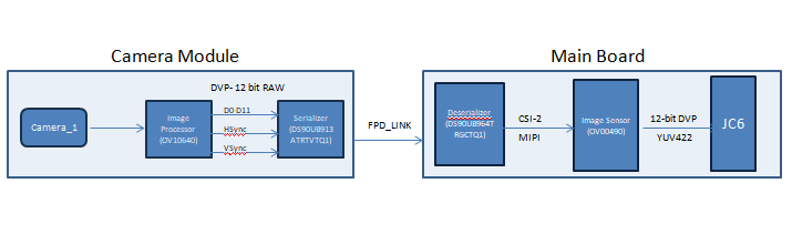
We have built  camera module using TIDA-00421 gerber from TI. We are using DS90UB964 deserialiser on our main board. Serialiser and deserialisers are connected using FPD link-III.

After image sensor and SerDes configuration we are able to see data at image sensor output (Oscilloscope probe). But we do not see data at serialiser and deserialiser output. 

Since we are able to see output from image sensor we assume we are missing something in SerDes configuration.

Below are the SerDes commands used as per our requirement. Could you check and suggest if we are missing out any configuration.?

Note: Deserialiser ID(DS90UB964)- 0x30

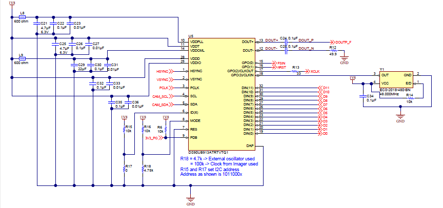
          Serialiser ID (DS90UB913)- 0x5d

.........................................................................

sleep 2;

i2cset -f -y 0 0x30 0x01 0x02;


sleep 2;
i2cset -f -y 0 0x30 0x0c 0xcf;

sleep 2;

i2cset -f -y 0 0x30 0x1f 0x00;
sleep 2;

i2cset -f -y 0 0x30 0x10 0x91;

sleep 2;
i2cset -f -y 0 0x30 0x11 0x85;

sleep 2;
i2cset -f -y 0 0x30 0x13 0x89;

sleep 2;
i2cset -f -y 0 0x30 0x14 0x8d;

sleep 2;
i2cset -f -y 0 0x30 0x19 0x00;

sleep 2;
i2cset -f -y 0 0x30 0x1a 0x8B;

sleep 2;
i2cset -f -y 0 0x30 0x1b 0x04;

sleep 2;
i2cset -f -y 0 0x30 0x1c 0xE2;
echo "half way through"
sleep 2;
i2cset -f -y 0 0x30 0x18 0x01;

sleep 2;
i2cset -f -y 0 0x30 0x4c 0x01;

sleep 2;
i2cset -f -y 0 0x30 0x58 0x58;

sleep 2;
i2cset -f -y 0 0x30 0x5c 0xbb;

sleep 2;
i2cset -f -y 0 0x30 0x5d 0x60;

sleep 2;
i2cset -f -y 0 0x30 0x6d 0x7e;

sleep 2;
i2cset -f -y 0 0x30 0x65 0x63;

sleep 2;
i2cset -f -y 0 0x30 0x7c 0xe0; 

sleep 2;
i2cset -f -y 0 0x30 0x70 0x2b;

sleep 2;
i2cset -f -y 0 0x30 0x71 0x2c;

sleep 2;
i2cset -f -y 0 0x30 0x0a 0x16;

sleep 2;
i2cset -f -y 0 0x30 0x0b 0x16;

sleep 2;
i2cset -f -y 0 0x5d 0x01 0x31;

sleep 2;
i2cset -f -y 0 0x5d 0x03 0xc5;

sleep 2;
i2cset -f -y 0 0x5d 0x0d 0x55;

sleep 2;
i2cset -f -y 0 0x5d 0x11 0x16;

sleep 2;
i2cset -f -y 0 0x5d 0x12 0x16;

sleep 2;

i2cset -f -y 0 0x30 0x4c 0x0f;

sleep 2;
i2cset -f -y 0 0x30 0x0f 0x00;

sleep 2;
i2cset -f -y 0 0x30 0x6e 0x9a;

sleep 2;
i2cset -f -y 0 0x30 0x32 0x12;
echo "almost there"
sleep 2;
i2cset -f -y 0 0x30 0x33 0x03;

sleep 2;
i2cset -f -y 0 0x30 0x20 0xfc;

sleep 2;
i2cset -f -y 0 0x30 0x20 0x0c;

sleep 2;
i2cset -f -y 0 0x30 0x21 0x14;

i2cset -f -y 0 0x5d 0x03 0xc5;
i2cset -f -y 0 0x5d 0x0d 0x55;
i2cset -f -y 0 0x5d 0x11 0x16;
i2cset -f -y 0 0x5d 0x12 0x16;

................................................................................

Regards

Bharati

  • Hello Bharati,

    a) Could you please upload a simple block diagram of your setup?
    b) Did you check lock status between the deserializer and serializer?
    c) Suggest you connect ALP to the deserilizer I2C port and check if you are able to see serializer as partner device in Info tab. Please upload a screen shot of the info tab. You can refer DS90UB964EVM user guide for help.
    d) Have you verified all i2c read/writes are happening without error? Please check from ALP first (either through register window or from scripting tab) that i2c access are fine.
    e) How are the 964 GPIOs connected? Pleas show a snippet of your schematic showing only 964, 913 connections.

    Thanks,
    Vishy
  • Hi Vishy

    Thank you for your quick response.


    a) Could you please upload a simple block diagram of your setup? 

    > We are connecting 4 camera modules to one deserialiser. Presently we are connecting Camera_1 only for testing. We are using below mentioned formats for serialiser input/output and Deserialiser input/output.

    b) Did you check lock status between the deserializer and serializer? 

    >Yes I have checked LOCK status on 0x4D register of deserialiser and it shows receiver input has met PASS criteria and receiver is Locked to incoming data. Below is the command read for your reference.

    => i2c md 0x30 0x4d;
    004d: 13 04 30 00 00 00 00 00 00 00 00 18 00 00 ba 00 ..0.............


    c) Suggest you connect ALP to the deserilizer I2C port and check if you are able to see serializer as partner device in Info tab. Please upload a screen shot of the info tab. You can refer DS90UB964EVM user guide for help.

    > As you can see in commands attached in my last message we are able to detect the serialiser and read & write into serialiser registers. So we understand deserialiser is detecting serialiser as its SerDes partner. Correct me if wrong.

    d) Have you verified all i2c read/writes are happening without error? Please check from ALP first (either through register window or from scripting tab) that i2c access are fine. 

    > We are not getting any error while reading or writing to any register. Please suggest if there is any special register that we need to try here to confirm this. (We are reading and writing using minicom or Teraterm. we do not have ALP)

    e) How are the 964 GPIOs connected? Pleas show a snippet of your schematic showing only 964, 913 connections.

    > we are not connecting 964 GPIO's anywhere. They are left open. Attaching the schematics for your reference.

    Regards

    Bharati

  • Hi Vishy,

    As per updated status, we tried some more register settings in serialiser. But still we are not seeing any data at deserialiser output.
    Below are the commands added newly for serialiser registers.

    i2cset -f -y 0 0x5d 0x01 0x00; //Auto voltage control disabled, Power=1.8V
    i2cset -f -y 0 0x5d 0x03 0xc1; //CLK to PLL is defined through MODE pin
    i2cset -f -y 0 0x5d 0x05 0x10; // Status of MODE is up to date from DES

    i2cset -f -y 0 0x5d 0x06 0x30; //DES_ID
    i2cset -f -y 0 0x5d 0x07 0x30; //DES Alias

    i2cset -f -y 0 0x5d 0x0d 0x11; // GPIO enable
    i2cset -f -y 0 0x5d 0x0e 0x11; // GPIO enable

    i2cset -f -y 0 0x5d 0x14 0x02; //CLK source for 12 bit LF mode 50MHz


    Regards
    Bharati
  • Hello Bharati,

    Thanks for confirming lock status.
    I have captured below initializations required
    a) Initialize UB964 deserializer first
    - initialize rx_port_ctl (0x0C) to match your port setup
    - initialize FPD3_PORT_SEL register (0x4C) port read/write bits
    - Confirm serializer address in serializer ID register (0x5B): this gets set when the serdes is locked
    - initialize ser_alias_id register (0x5C) (soc code uses this id to access serializer)
    - initialize slaveID[0] (0x5D) to imager address
    - initialize slaveAlias[0] (0x65) to imager (soc code uses this id to access imager)
    - initalize BCC_CONFIG (0x58) (all serializer/imager initializations go through back channel) to 0x58
    - initialize PORT_CONFIG (0x6D) coax_mode, fpd3_mode (could be done through mode pin also)
    - to begin keep default values for 0x70, 0x71
    - initialize csi_ctl (0x33): enable csi, clock, number of lanes (note this should match csi rx of your imager)
    - initialize csi_pll_ctl (0x1F): csi_tx_speed should match your csi_rx speed of your imager
    - initialize FWD_CTL1 (0x20) and FWD_CTL2 (0x21): finally enable forwarding (see DS section 8.4.19)
    b) Initialize UB913 serializer next
    - make sure mode pin is configured properly
    - make sure GPIOs are configured properly according to your setup
    -
    c) Finally initialize the image sensor registers (OV10640)

    d) Regarding your code:
    - please follow the initialization sequence I outline above
    - Not sure why deserializer GPIO registers 0x10, 0x11, 0x13, 0x14 are initialized
    - frame sync register (0x19-0x1C) initialization not required now; only when you are testing multiple cameras
    - if i2c is working, you can leave 0x0A and 0x0B registers default

    There are some advantages using ALP :
    a) Using ALP you can debug and confirm each portion of the link is first working. For example, after checking lock, you can check FPD link transfers between 913 and 964 is happening (without imager & SOC connected) without errors (CRC & Parity) by running BIST script. This is a python script that's part of ALP install folder (below) and you can run it from scripting tab
    C:\Program Files (x86)\Texas Instruments\Analog LaunchPAD v1.57.0010\PreDefScripts\DS90UB964
    b) You can initialize Patgen on the 964 to send out test patterns (CSI frames) and check 964 CSI TX port connection
    c) You can connect ALP to 913 and check imager to 913 communication link. Check if all the status bits are looking fine.

    Thanks,
    Vishy
  • Few more comments:
    a) In the 964 deserializer initialization steps: There's also register CSI_port_sel (0x32) that has to be initialized before writing 0x33.
    b) In your code, I think you are initializing GPIO pins to bring out lock status, so that's ok. Please ignore my comment on that above.
    c) Note: Deserializer Register RX port initializations 0x4C, 0x58, 0x5C, 0x5D, 0x65, 0x6D, 0x6e, 0x7D has to be done for each port. Initially of course only for the first camera port you are testing.

    Thanks,
    Vishy
  • Hi Vishy,

    I have changed sequence as per your recommendation but I do not see any change in the SerDes behavior. I do not see any waveform at CSI2 output port0.

    From the above commands , I tried with some other values in some of the registers as below
    i2cset -f -y 0 0x30 0x6d 0x75; //Changed from 7e
    i2cset -f -y 0 0x30 0x32 0x10; //changed from 12
    i2cset -f -y 0 0x30 0x1f 0x02; //changed from 00
    i2cset -f -y 0 0x30 0x20 0xec; //Changed from 0c
    i2cset -f -y 0 0x30 0x21 0x01; //changed from 14


    Please check if the serialiser register settings are proper in above commands. We have changed only deserialiser sequence as per your suggestions.


    Regards
    Bharati
  • Bharati,

    1. Serializer GPO1 is connected to the imager reset. In addition to enabling the GPO, you should  reset the imager

    a) Set the reset pin high

    b) Set the pin low (wait for some time)

    c) Set the pin high

    Then initialize the imager. Are you initializing the imager registers? Don't have to upload imager initialization but just want to be sure you are doing it. Please double check what's the frame rate, data type, etc it is set for. Overall imager data rate (hor resolution x ver resolution x frame rate x #bits per frame x blanking overhead) must be within what 913 can support.

    2. Please double check how other GPOs are used and keep them high or low as per imager specification

    3. Check in serializer register 0x0C PCLK is detected

    4. Run BIST code (if you are not using ALP make your own version from the Python code or DS sample) and check FPD link is fine

    5. Initialize Run Patgen from UB964 to check test patterns can be seen on CSI Port. I enclose below an example RAW12 UB964 Patgen script. See the DS for more info on the Patgen

    Thanks,

    Vishy

    RAW12_patgen.py
    # 1920*1080 @ 30 fps
     # 4 x lane 800Mbps/lane
     # Data Type: RAW12
    
     # Data
     #
     # Hactive:1920 pixles
     # Vactive:1080 lines
     # Vtotal:1125 lines
     # Vfront:10 lines
     # Vback:33 lines
     # Pixel size: 12 bits (Mipi CSI-2, Table 25 )
     # Block size: 3 bytes (Mipi CSI-2, Table 25 )
     # Frame rate: 30 fps
     # Number of bars: 8
     #
     # Reset
     board.WriteReg(0x01, 0x01)
     # Set CSI_TX_SPEED to select 800Mbps
     board.WriteReg(0x1F, 0x02)
     #
     #
     # CSI sel and CSI enable
     board.WriteReg(0x32, 0x01) # CSI0 sel and CSI0 enable
     time.sleep(0.5)
     board.WriteReg(0x33, 0x03) # CSI_LANE_COUNT: 4, EN Continuous Clock
     time.sleep(0.5)
    
     board.WriteReg(0x21, 0x80) # Enable CSI Replicate Mode
     
     # enable pat gen
     board.WriteReg(0xB0, 0x00) # Indirect Pattern Gen Registers
     board.WriteReg(0xB1, 0x01) # PGEN_CTL
     board.WriteReg(0xB2, 0x01)
    
     board.WriteReg(0xB1, 0x02) # PGEN_CFG
     board.WriteReg(0xB2, 0x33) # NUM_CBARS, Block_size
    
     board.WriteReg(0xB1, 0x03) # PGEN_CSI_DI
     board.WriteReg(0xB2, 0x2C) # RAW12 Data Type
    
     board.WriteReg(0xB1, 0x04) # PGEN_LINE_SIZE1: 1920*12/8=2880
     board.WriteReg(0xB2, 0x0B)
    
     board.WriteReg(0xB1, 0x05) # PGEN_LINE_SIZE0: 1920*12/8=2880
     board.WriteReg(0xB2, 0x40)
    
     board.WriteReg(0xB1, 0x06) # PGEN_BAR_SIZE1: 1920*12/8/8)=360
     board.WriteReg(0xB2, 0x01)
    
     board.WriteReg(0xB1, 0x07) # PGEN_BAR_SIZE0: 1920*12/8/8)=360
     board.WriteReg(0xB2, 0x68)
    
     board.WriteReg(0xB1, 0x08) # PGEN_ACT_LPF1: 1080
     board.WriteReg(0xB2, 0x04)
    
     board.WriteReg(0xB1, 0x09) # PGEN_ACT_LPF0: 1080
     board.WriteReg(0xB2, 0x38)
    
     board.WriteReg(0xB1, 0x0a) # PGEN_TOT_LPF1: 1125
     board.WriteReg(0xB2, 0x04)
    
     board.WriteReg(0xB1, 0x0b) # PGEN_TOT_LPF0: 1125
     board.WriteReg(0xB2, 0x65)
     
     board.WriteReg(0xB1, 0x0c) # PGEN_LINE_PD1:1/(30*1125*10ns)=2963
     board.WriteReg(0xB2, 0x0B)
    
     board.WriteReg(0xB1, 0x0d) # PGEN_LINE_PD0:1/(30*1125*10ns)=2963
     board.WriteReg(0xB2, 0x93)
    
     board.WriteReg(0xB1, 0x0E) # PGEN_VBP: 33
     board.WriteReg(0xB2, 0x21)
    
     board.WriteReg(0xB1, 0x0F) # PGEN_VFP: 10
     board.WriteReg(0xB2, 0x0A)

  • Hi Vishy,

    Thanks for your inputs on Image sensor.
    Your critical insights are helping us immensely.
    Today we focused on SerDes configuration only to make sure FPD link is proper.

    To confirm this we have done following experiments with Pattern Generator attached by you.
    1) Pattern generation from deserialiser
    >Enable CSI output port
    >Set CSI port speed to 800Mbps
    >Send pattern generation commands. Copying the commands below

    i2cset -f -y 0 0x30 0x32 0x01; # CSI0 sel and CSI0 enable
    i2cset -f -y 0 0x30 0x33 0x01;
    i2cset -f -y 0 0x30 0xB0 0x00;# Indirect Pattern Gen Registers
    i2cset -f -y 0 0x30 0xB1 0x01; # PGEN_CTL
    i2cset -f -y 0 0x30 0xB2 0x01;
    i2cset -f -y 0 0x30 0xB1 0x02; # PGEN_CFG
    i2cset -f -y 0 0x30 0xB2 0x33;
    i2cset -f -y 0 0x30 0xB1 0x03; # PGEN_CSI_DI
    i2cset -f -y 0 0x30 0xB2 0x24;
    i2cset -f -y 0 0x30 0xB1 0x04; # PGEN_LINE_SIZE1
    i2cset -f -y 0 0x30 0xB2 0x0F;
    i2cset -f -y 0 0x30 0xB1 0x05; # PGEN_LINE_SIZE0
    i2cset -f -y 0 0x30 0xB2 0x00;
    i2cset -f -y 0 0x30 0xB1 0x06; # PGEN_BAR_SIZE1
    i2cset -f -y 0 0x30 0xB2 0x01;
    i2cset -f -y 0 0x30 0xB1 0x07; # PGEN_BAR_SIZE0
    i2cset -f -y 0 0x30 0xB2 0xE0;
    i2cset -f -y 0 0x30 0xB1 0x08; # PGEN_ACT_LPF1
    i2cset -f -y 0 0x30 0xB2 0x02;
    i2cset -f -y 0 0x30 0xB1 0x09; # PGEN_ACT_LPF0
    i2cset -f -y 0 0x30 0xB2 0xD0;
    i2cset -f -y 0 0x30 0xB1 0x0A; # PGEN_TOT_LPF1
    i2cset -f -y 0 0x30 0xB2 0x04;
    i2cset -f -y 0 0x30 0xB1 0x0B; # PGEN_TOT_LPF0
    i2cset -f -y 0 0x30 0xB2 0x1A;
    i2cset -f -y 0 0x30 0xB1 0x0C; # PGEN_LINE_PD1
    i2cset -f -y 0 0x30 0xB2 0x0C;
    i2cset -f -y 0 0x30 0xB1 0x0D; # PGEN_LINE_PD0
    i2cset -f -y 0 0x30 0xB2 0x67;
    i2cset -f -y 0 0x30 0xB1 0x0E; # PGEN_VBP
    i2cset -f -y 0 0x30 0xB2 0x21;
    i2cset -f -y 0 0x30 0xB1 0x0F; # PGEN_VFP
    i2cset -f -y 0 0x30 0xB2 0x0A

    >Once the commands are executed, we are able to see the signals at CSI port at deserialiser output.

    2)Pattern Generation from Serialiser.
    >Enable CSI port
    >Set speed to 800Mbps
    >Enable BIST mode
    i2cset -f -y 0 0x30 0xb3 0x81;
    >Send pattern generator commands.(Same commands which are copied above)
    >After executing these commands we are able to see signals at CSI port of deserialiser output
    >We are reading 0x4d register of deserialiser to check error status, PASS indication and FPD LOCK status. We are reading 0x13.(No errors, met PASS criteria,LOCKed to receiver data)

    With this we assume that the pattern generated is from the serialiser and FPD link is working. Please confirm if we are correct.
    Or is there any register in serialiser to confirm proper working of serialiser.

    Once we confirm the path from J6 to serializer using pattern generator, we will focus on OV10640 configs and it's alignment with respect to serializer.
    Please let us know if we need to do anymore experiments to confirm that the serializer pattern generator is working.

    Waiting for your valuable reply.
  • >>>With this we assume that the pattern generated is from the serialiser and FPD link is working. Please confirm if we are correct.

    a) Unfortunately no. There's no Patgen module in 913. Patgen module support is there in 954 and so it can be used to validate only 954 CSI output link.
    b) To test from serializer, you have to use only BIST. Please install ALP and take a look at the script in the folder I mention above. You have to follow the initialization used there and monitor as explained in that Python script.
    c) Turn off 954 patgen (or do a complete reset) before running BIST.

    Thanks,
    Vishy
  • Hi Vishy,

    We have downloaded ALP and listing the observations below

    > After launching ALP, we are able to see 964 and remote device as 913.

    >We tried with the script sent by you in previous mail, it shows syntax error

    > We are able to see 913 in Remote Register tab (0x0: DS90UB913). But when we try to write into serialiser register it is not getting written (It becomes 00 when I click on apply). We are able to write in all deserialiser registers

    >We just enabled BIST mode by writing 43 in 0xB3 register of deserialiser. After this we are seeing below information in information tab. Frequency is changing to 53MHz. But we are not able to see any test pattern at deserialiser output.

    Note: Through Linux I2C commands we are able to detect and read write into serialiser and imager registers.

    Is this the expected behavior ? If not how else do we confirm working of serialiser and FPD link? 

    Attaching register reads from Deserialisers and Serialisers.

    Please suggest how do we move forward with this.

    Regards

    Bharati

  • ALP_DES_REG.txt
    Register Display - ALP Nano 1 - DS90UB964, Connector 1
    
    Register	Data	Name
    0x0000	0x60	I2C_DEVICE_ID
    0x0001	0x00	RESET_CTL
    0x0002	0x1E	GENERAL_CFG
    0x0003	0x30	REV_MASK_ID
    0x0004	0xC2	DEVICE_STS
    0x0005	0x01	PAR_ERR_THOLD1
    0x0006	0x00	PAR_ERR_THOLD0
    0x0007	0xFE	BCC Watchdog Control
    0x0008	0x1C	I2C Control 1
    0x0009	0x10	I2C Control 2
    0x000A	0x79	SCL High Time
    0x000B	0x79	SCL Low Time
    0x000C	0x01	RX_PORT_CTL
    0x000D	0xB9	IO_CTL
    0x000E	0x00	GPIO_PIN_STS
    0x000F	0xFF	GPIO_INPUT_CTL
    0x0010	0x00	GPIO0_PIN_CTL
    0x0011	0x00	GPIO1_PIN_CTL
    0x0012	0x00	GPIO2_PIN_CTL
    0x0013	0x00	GPIO3_PIN_CTL
    0x0014	0x00	GPIO4_PIN_CTL
    0x0015	0x00	GPIO5_PIN_CTL
    0x0016	0x00	GPIO6_PIN_CTL
    0x0017	0x00	GPIO7_PIN_CTL
    0x0018	0x00	FS_CTL
    0x0019	0x00	FS_HIGH_TIME_1
    0x001A	0x00	FS_HIGH_TIME_0
    0x001B	0x00	FS_LOW_TIME_1
    0x001C	0x00	FS_LOW_TIME_0
    0x001D	0x00	MAX_FRM_HI
    0x001E	0x04	MAX_FRM_LO
    0x001F	0x02	CSI_PLL_CTL
    0x0020	0xE0	FWD_CTL1
    0x0021	0x03	FWD_CTL2
    0x0022	0x00	FWD_STS
    0x0023	0x00	INTERRUPT_CTL
    0x0024	0x00	INTERRUPT_STS
    0x0025	0x00	TS_CONFIG
    0x0026	0x00	TS_CONTROL
    0x0027	0x00	TS_LINE_HI
    0x0028	0x00	TS_LINE_LO
    0x0029	0x00	TS_STATUS
    0x002A	0x00	TIMESTAMP_P0_HI
    0x002B	0x00	TIMESTAMP_P0_LO
    0x002C	0x00	TIMESTAMP_P1_HI
    0x002D	0x00	TIMESTAMP_P1_LO
    0x002E	0x00	TIMESTAMP_P2_HI
    0x002F	0x00	TIMESTAMP_P2_LO
    0x0030	0x00	TIMESTAMP_P3_HI
    0x0031	0x00	TIMESTAMP_P3_LO
    0x0032	0x00	CSI_PORT_SEL
    0x0033	0x43	CSI_CTL
    0x0034	0x00	CSI_CTL2
    0x0035	0x00	CSI_STS
    0x0036	0x00	CSI_TX_ICR
    0x0037	0x00	CSI_TX_ISR
    0x0038	0x00	Reserved
    0x0039	0x00	Reserved
    0x003A	0x00	Reserved
    0x0040	0x00	Reserved
    0x0041	0xA3	Reserved
    0x0042	0x01	AEQ_CTL
    0x0043	0x01	AEQ_ERR_THOLD
    0x004C	0x01	FPD3_PORT_SEL
    0x004D	0x03	RX_PORT_STS1
    0x004E	0x04	RX_PORT_STS2
    0x004F	0x35	RX_FREQ_HIGH
    0x0050	0x19	RX_FREQ_LOW
    0x0051	0x00	Reserved
    0x0052	0x00	Reserved
    0x0053	0x00	Reserved
    0x0054	0x00	Reserved
    0x0055	0x00	RX_PAR_ERR_HI
    0x0056	0x00	RX_PAR_ERR_LO
    0x0057	0x00	BIST_ERR_COUNT
    0x0058	0x18	BCC_CONFIG
    0x0059	0x00	DATAPATH_CTL1
    0x005A	0x00	DATAPATH_CTL2
    0x005B	0xBA	SER_ID
    0x005C	0x00	SER_ALIAS_ID
    0x005D	0x00	SlaveID[0]
    0x005E	0x00	SlaveID[1]
    0x005F	0x00	SlaveID[2]
    0x0060	0x00	SlaveID[3]
    0x0061	0x00	SlaveID[4]
    0x0062	0x00	SlaveID[5]
    0x0063	0x00	SlaveID[6]
    0x0064	0x00	SlaveID[7]
    0x0065	0x00	SlaveAlias[0]
    0x0066	0x00	SlaveAlias[1]
    0x0067	0x00	SlaveAlias[2]
    0x0068	0x00	SlaveAlias[3]
    0x0069	0x00	SlaveAlias[4]
    0x006A	0x00	SlaveAlias[5]
    0x006B	0x00	SlaveAlias[6]
    0x006C	0x00	SlaveAlias[7]
    0x006D	0x7D	PORT_CONFIG
    0x006E	0x88	BC_GPIO_CTL0
    0x006F	0x88	BC_GPIO_CTL1
    0x0070	0x2B	RAW10_ID
    0x0071	0x2C	RAW12_ID
    0x0072	0xE4	Reserved
    0x0073	0x00	LINE_COUNT_1
    0x0074	0x00	LINE_COUNT_0
    0x0075	0x00	LINE_LEN_1
    0x0076	0x00	LINE_LEN_0
    0x0077	0xC5	FREQ_DET_CTL
    0x0078	0x00	MAILBOX_1
    0x0079	0x01	MAILBOX_2
    0x007A	0x00	CSI_RX_STS
    0x007B	0x00	Reserved
    0x007C	0x20	PORT_CONFIG2
    0x007D	0x00	PORT_PASS_CTL
    0x007E	0x00	Reserved
    0x00B0	0x00	IND_ACC_CTL
    0x00B1	0x00	IND_ACC_ADDR
    0x00B2	0x00	IND_ACC_DATA
    0x00B3	0x43	BIST_CTL
    0x00B4	0x25	Reserved
    0x00B5	0x00	Reserved
    0x00B6	0x18	Reserved
    0x00B7	0x00	Reserved
    0x00B8	0x89	MODE_IDX_STS
    0x00B9	0x03	Reserved
    0x00BA	0x03	Reserved
    0x00BB	0x74	Reserved
    0x00BC	0x80	FV_MIN_TIME
    0x00BD	0x00	Reserved
    0x00BE	0x00	GPIO_PD_CTL
    0x00D0	0x20	Reserved
    0x00D1	0x43	Reserved
    0x00D2	0x84	AEQ_TEST
    0x00D3	0x0F	AEQ_STATUS
    0x00D4	0x60	AEQ_BYPASS
    0x00D5	0xF8	AEQ_MIN_MAX
    0x00D6	0x07	Reserved
    0x00D7	0x00	Reserved
    0x00D8	0x00	PORT_ICR_HI
    0x00D9	0x00	PORT_ICR_LO
    0x00DA	0x00	PORT_ISR_HI
    0x00DB	0x00	PORT_ISR_LO
    0x00F0	0x5F	FPD3_RX_ID0
    0x00F1	0x55	FPD3_RX_ID1
    0x00F2	0x42	FPD3_RX_ID2
    0x00F3	0x39	FPD3_RX_ID3
    0x00F4	0x36	FPD3_RX_ID4
    0x00F5	0x34	FPD3_RX_ID5
    0x00F8	0x00	I2C_RX0_ID
    0x00F9	0x00	I2C_RX1_ID
    0x00FA	0x00	I2C_RX2_ID
    0x00FB	0x00	I2C_RX3_ID
    
    ALP_SER_REG.txt
    Register Display - ALP Nano 1 - DS90UB913, Connector 1
    
    Register	Data	Name
    0x0000	0x00	I2C Device ID (0x00)
    0x0001	0x00	Power and Reset (0x01)
    0x0003	0x00	General Configuration (0x02)
    0x0004	0x00	Reserved
    0x0005	0x00	Mode Select (0x03)
    0x0006	0x00	DES ID (0x04)
    0x0007	0x00	DESAlias (0x05)
    0x0008	0x00	SlaveID (0x06)
    0x0009	0x00	SlaveAlias (0x07)
    0x000A	0x00	CRC Errors (0x08)
    0x000B	0x00	CRC Errors (0x09)
    0x000C	0x00	General Status (0x0A)
    0x000D	0x00	GPIO[0] and GPIO[1] Config (0x0B)
    0x000E	0x00	GPIO[2] and GPIO[3] Config (0x0C)
    0x000F	0x00	I2C Master Config (0x0D)
    0x0010	0x00	I2C Control (0x0E)
    0x0011	0x00	SCL High Time (0x0F)
    0x0012	0x00	SCL Low Time (0x10)
    0x0013	0x00	General Purpose Control (0x11)
    0x0014	0x00	BIST and DOPL Control (0x12)
    0x0016	0x00	RESERVED
    0x001E	0x00	BCC Watchdog Control (0x1E)
    0x0023	0x00	RESERVED
    0x0029	0x00	Reserved
    0x002A	0x00	CRC Errors (0x18)
    0x0035	0x00	PLL CLK OV (0x24)
    

  • Hello,

    a) Please check your board setup and link. I don't see on the ALP info tab 913 under partner information. Please refer UB964EVM user guide.

    b) Once you have debugged your setup and link (and see UB913 in Info tab), then you run from scripting tab BIST script. You can find the BIST script in the following folder:
    C:\Program Files (x86)\Texas Instruments\Analog LaunchPAD v1.57.0010\PreDefScripts\DS90UB964

    Script name is
    P964_913A_BIST_AllPorts.py

    Thanks
    Vishy
  • Here's how info tab partner information should look like

    I also enclose the patgen script again (there was an extra space beginning of each line)

    Thanks

    2350.RAW12_patgen.py
    # 1920*1080 @ 30 fps
     # 4 x lane 800Mbps/lane
     # Data Type: RAW12
    
     # Data
     #
     # Hactive:1920 pixles
     # Vactive:1080 lines
     # Vtotal:1125 lines
     # Vfront:10 lines
     # Vback:33 lines
     # Pixel size: 12 bits (Mipi CSI-2, Table 25 )
     # Block size: 3 bytes (Mipi CSI-2, Table 25 )
     # Frame rate: 30 fps
     # Number of bars: 8
     #
     # Reset
    board.WriteReg(0x01, 0x01)
     # Set CSI_TX_SPEED to select 800Mbps
    board.WriteReg(0x1F, 0x02)
     #
     #
     # CSI sel and CSI enable
    board.WriteReg(0x32, 0x01) # CSI0 sel and CSI0 enable
    time.sleep(0.5)
    board.WriteReg(0x33, 0x03) # CSI_LANE_COUNT: 4, EN Continuous Clock
    time.sleep(0.5)
    
    board.WriteReg(0x21, 0x80) # Enable CSI Replicate Mode
     
     # enable pat gen
    board.WriteReg(0xB0, 0x00) # Indirect Pattern Gen Registers
    board.WriteReg(0xB1, 0x01) # PGEN_CTL
    board.WriteReg(0xB2, 0x01)
    
    board.WriteReg(0xB1, 0x02) # PGEN_CFG
    board.WriteReg(0xB2, 0x33) # NUM_CBARS, Block_size
    
    board.WriteReg(0xB1, 0x03) # PGEN_CSI_DI
    board.WriteReg(0xB2, 0x2C) # RAW12 Data Type
    
    board.WriteReg(0xB1, 0x04) # PGEN_LINE_SIZE1: 1920*12/8=2880
    board.WriteReg(0xB2, 0x0B)
    
    board.WriteReg(0xB1, 0x05) # PGEN_LINE_SIZE0: 1920*12/8=2880
    board.WriteReg(0xB2, 0x40)
    
    board.WriteReg(0xB1, 0x06) # PGEN_BAR_SIZE1: 1920*12/8/8)=360
    board.WriteReg(0xB2, 0x01)
    
    board.WriteReg(0xB1, 0x07) # PGEN_BAR_SIZE0: 1920*12/8/8)=360
    board.WriteReg(0xB2, 0x68)
    
    board.WriteReg(0xB1, 0x08) # PGEN_ACT_LPF1: 1080
    board.WriteReg(0xB2, 0x04)
    
    board.WriteReg(0xB1, 0x09) # PGEN_ACT_LPF0: 1080
    board.WriteReg(0xB2, 0x38)
    
    board.WriteReg(0xB1, 0x0a) # PGEN_TOT_LPF1: 1125
    board.WriteReg(0xB2, 0x04)
    
    board.WriteReg(0xB1, 0x0b) # PGEN_TOT_LPF0: 1125
    board.WriteReg(0xB2, 0x65)
     
    board.WriteReg(0xB1, 0x0c) # PGEN_LINE_PD1:1/(30*1125*10ns)=2963
    board.WriteReg(0xB2, 0x0B)
    
    board.WriteReg(0xB1, 0x0d) # PGEN_LINE_PD0:1/(30*1125*10ns)=2963
    board.WriteReg(0xB2, 0x93)
    
    board.WriteReg(0xB1, 0x0E) # PGEN_VBP: 33
    board.WriteReg(0xB2, 0x21)
    
    board.WriteReg(0xB1, 0x0F) # PGEN_VFP: 10
    board.WriteReg(0xB2, 0x0A)

  • Hi Vishy,

    Thanks for your valuable reply.
    We have started debugging the FPDLink - UB913 Ser side.
    We will update our analysis soon.


    Thanks,
    Bharati