This thread has been locked.

If you have a related question, please click the "Ask a related question" button in the top right corner. The newly created question will be automatically linked to this question.

SN65HVD75: Power supply glitch due to RS-485 driver

Part Number: SN65HVD75

Hi,

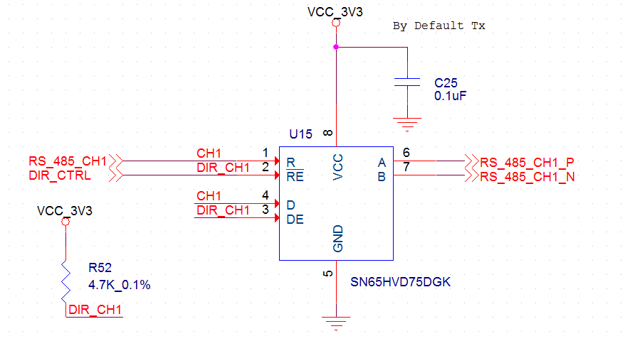
In my board, i have SN65HVD75DGK device and its configured as driver. 

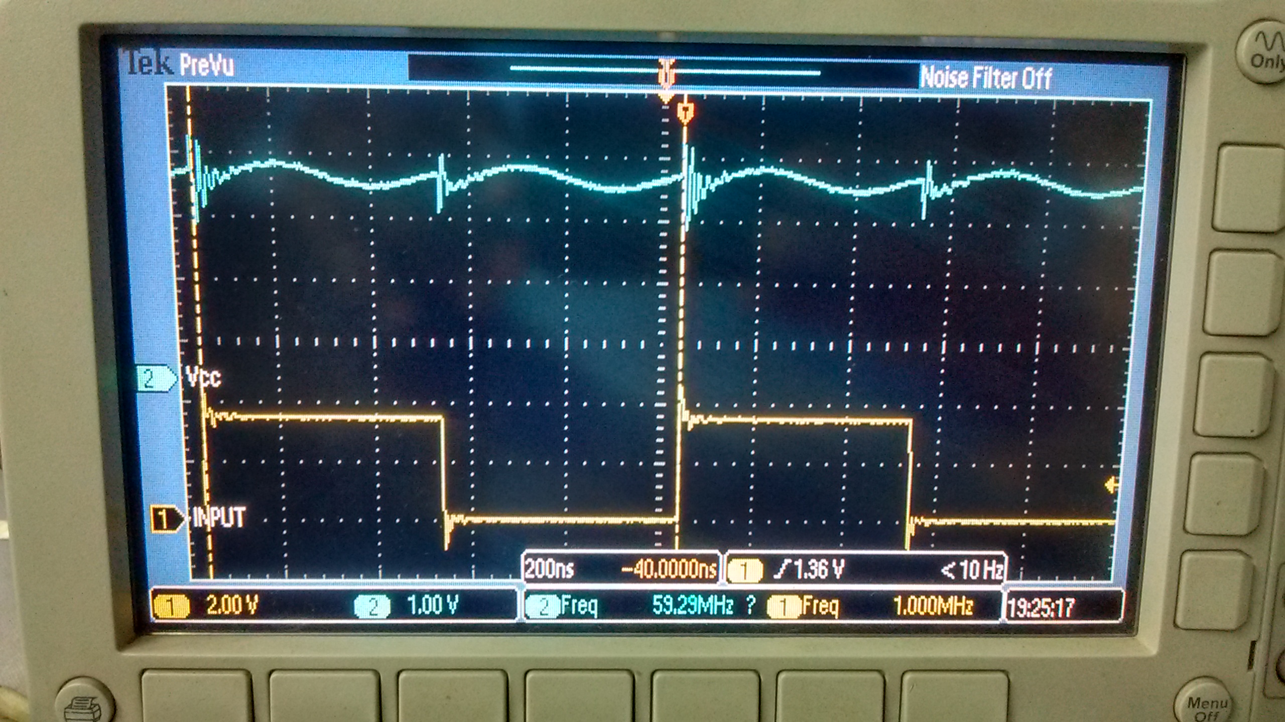
While this driver is in operating condition, i am observing power rail (VCC) glitch (Operating frequency 1MHz).

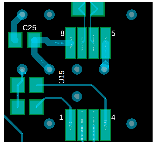
Please refer below schematic and oscilloscope image for reference.

What could be the reason for this & how to rectify ?? 

Input signal and VCC are captured below.

  • Ramesh,

    Can you check the supply to see if there is any current limiting? If possible, it would be helpful to capture Icc waveform as well. You may also want to check the routing of supply and ground to see if they're low impedance. Please let me know if you get any more information.

    Regards,
    Hao
  • Hi Hao,

    I have checked current limit and it was well above the range (4 Amps approx).

    Icc current consumption measured by digital multi-meter and it was 2mA @1MHz input.

    Below you can see routing of supply and ground...

    Thanks,

    Ramesh M

  • Ramesh,

    I forgot to ask last time. Do you have any resistor termination on the bus? Where does the supply come from, LDO or DCDC? Your layout looks well to me, except that bus routing might be too narrow (we prefer 120Ohm impedance). Seeing the supply ripples, I suspect it has to do something with transient current. Therefore it would be helpful to check the current during the transition.

    Regards,
    Hao

  • Hao,

    Yes, we have 120E termination on the bus.

    Power supply(3.3V) is getting generated from LMZ31704RVQT DC-DC module.

    If the problem is with transient current then, how to measure and rectify the issue ??

    Regards,

    Ramesh

  • Hi Ramesh,

    Hao is out of the office today, so I can try to help. I agree with the idea that this noise is likely a response to a transient current from the RS-485 transceiver. As it changes its output state, there will be an abrupt change in supply current as the output driver circuitry switches the RS-485 bus's polarity. The magnitude of this transient current would depend on the transceiver design as well as the capacitive loading on the bus.

    Because this switching current is short in duration (likely exceeding the DC/DC regulator's loop bandwidth), it is typically sourced by the decoupling capacitance of the transceiver (or the output capacitance of the regulator if this is nearby). So, if you wanted to reduce the amplitude the ripple you may want to experiment with different decoupling capacitance values to make sure that the power supply's effective impedance is low across a wide frequency range. Sometimes this can involve placing multiple capacitances of different values or case sizes in parallel. You can read more about this in this app note: www.ti.com/.../slta055.pdf.

    Another thing you could try would be a ferrite bead in series with the VCC rail (between the regulator and the transceiver's decoupling capacitance). It looks like the lowest noise frequency is about 2 MHz, and ferrites can be effective in this range.

    If you were to revise the PCB layout, I would recommend making sure that the VCC net is routed as a plane or thick trace in order to maximize its mutual capacitance to ground and minimize its series resistance and inductance.

    Regards,
    Max