This thread has been locked.

If you have a related question, please click the "Ask a related question" button in the top right corner. The newly created question will be automatically linked to this question.

TPD1E05U06: TVS device comparison

Part Number: TPD1E05U06
Other Parts Discussed in Thread: TPD1E10B06, , TPD1E04U04

Hi team,

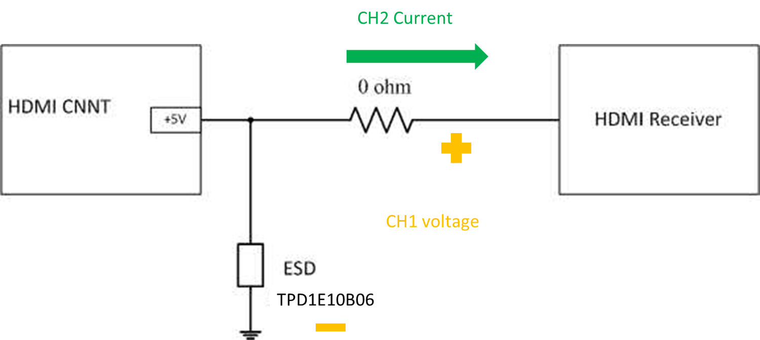
The below figure shows my customer's block diagram. RD use TPD1E10B06 to protect the HDMI receiver IC.

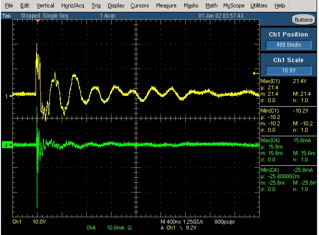
HDMI receiver IC burn out problem after MP. Their HDMI 5V connect to HDMI Receiver IC, Max rating is 5.3V.

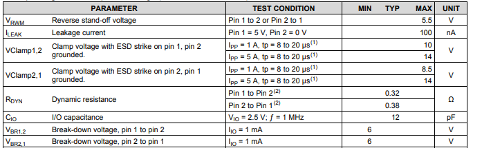
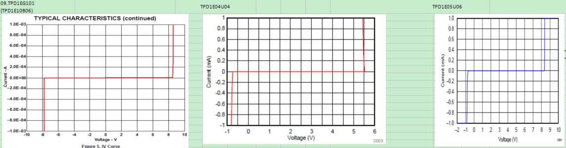
They think the ESD device need to have voltage limit (at about 5.3V) feature. As the below comparison picture of our TVS(TPD1E10B06, TPD1E04U04,TPD1E05U06 ). They think TPD1E04U04  is more suitable for them due to ESD starting to turn on.

But, TPD1E04U04 's stand-off voltage is only 3.6V and they will use it on a 5v HDMI rail. Is there suggestion from BU? Thanks.

Best Regards,

Ben

  • Hello,
    Can you explain what you mean by MP? Are you applying an ESD pulse or surge pulse on the pin?
  • Hi Cameron,

    Sorry for the not clear abbreviation. MP means mass production.

    Because there are some burn out problem on TPD1E10B06.

    So, the customer test the device by connecting to DC directly and hope the ESD device can clamp the voltage at near 5.3V which is Max rating HDMI Receiver IC.

    I am not very familiar with ESD protection but as my understanding, should ESD device not use to protect the DC level?

    Best Regards,

    Ben

  • Ben,

    You are correct that ESD diodes are not used to clamp DC events

  • Hi Cameron,

    The customer uses TPD1E10B06 to protect the HDMI receiver and face some burning out problem when they plugin HDMI cable of DVD player into HDMI connector.

    They measure the inrush voltage/current as below figure.

    Could you kindly reply these questions below?

    1. Can this inrush voltage/current be classified as Surge?

    2.Can TPD1E10B06 protect this inrush and protect the HDMI receiver in the back?

    Thanks,

    Ben

  • Hi Cameron,

    I am sorry for the bad question.

    Customer said this behavior and waveform doesn't burn out the receiver IC.

    I would like to consult with you about the behavior model of our TPD1E10B06. The test setup is as below block diagram.

    As my understanding, CH1's voltage will clamp at clamp voltage when the voltage is higher than breakdown voltage.

    In this waveform, we didn't see this behavior. So, customer ask why does this ESD didn't work normally in this situation.

    Here is one question about it:

    • Is the energy of this momentary voltage too small, causing ESD to be inactive? The below table in datasheet shows the VBR test condition is at 1mA. 


    Thanks for your kindly help. Please feel free to let me know, if you need anything else.

    Ben,

  • Ben,

    The device is clamping the event I believe because I see your waveform shows a maximum of 21V.

    If the receiver is not breaking after this ESD event that means the device protected the receiver.