This thread has been locked.

If you have a related question, please click the "Ask a related question" button in the top right corner. The newly created question will be automatically linked to this question.

Linux/SN65DSI84-Q1: Linux/SN65DSI84

Part Number: SN65DSI84-Q1
Other Parts Discussed in Thread: SN65DSI84, DSI-TUNER

Tool/software: Linux

Hi,

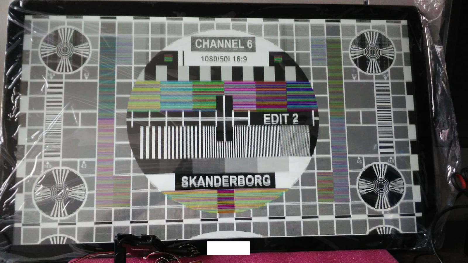
We are using SN65DSI84 in our hardware and we have implemented a MIPI to LVDS converter using this chip set. First we tested the video pattern generation and its working for us.

Now we are trying to display actual data from the mipi interface, but not able to see any data in the display.

So my query is do we need to initialize the SN65 with any MIPI commands from the Host CPU? Our host CPU is i.MX8 and OS is Linux.

Or the I2C initialization enough for the SN65?


Also , could you please share reference code for the SN65DSI84?

Currently we are referring the files panel-sn65dsix.c, sn65dsi8x_i2c.c & fsl-imx8mq-evk-dcss-sn65dsi8x.dts downloaded form the ti form.

Regards,

Bijesh V.M. 

  • Hi Bijesh,

    The DSI84 does not accept MIPI commands, it is just initialization via i2c. Please ensure that you're following the initialization sequence as listed in the datasheet. It is required for correct operation of the device.

    We do not have any current reference code but there is old reference code here: e2e.ti.com/.../2006135 It may implement an older version of the initialization sequence. You need to follow the sequence that is in the datasheet. You can also use the DSI-Tuner to help configure the register settings.

    Regards,
    I.K.
  • Hi,

    We got the display working but facing problem related to timing (attaching the image of the present display)  I would like to know the mathematical relation between the CHA_SYNC_DELAY, CHA_HSYNC_PULSE_WIDTH  & CHA_HOR_BACK_PORCH.

    Could you please provide this information?

    Values currently used is as given below.

    Our display is dual LVDS display 1920 * 1080.

    Porch settings: HBP& HFP: 130 pixels , HSW: 20 pixels , VSW: 5 lines, VBP: 20 lines , VFP: 20 lines

    Pixel clock frequency = (1920+20+130+130) * (1080+5+20+20)*60Hz= 148.5Mhz

    DSI CLK is 445.5Mhz, 4 lines. LVDS clock for each LVDS o/p channel is 148.5Mhz/2 = 74.25Mhz.

    In my case not able to increase the value of the register 0x2C, CHA_HSYNC_PULSE_WIDTH to 20 which is the value required for my display (High lighted in yellow)

    {0x09, 0x01}, /* SOFTRESET */
    {0x0D, 0x00}, /*PLL Disable */
    {0x0A, 0x05}, /* LVDS_CLK_Range bit 3:1 - value 010 – 62.5 MHz ≤ LVDS_CLK < 87.5 MHz, Display LVDS clock is 74.25Mhz */
    {0x0B, 0x28}, /* DSI_CLK_DIVIDER, devicde by 6 (DSI CLK is 445.5/6 = LVDS clk 74.25Mhz) */
    {0x10, 0x26}, /* DSI Ch Mode(bit6:5) 01 - single DSI, bit 4:3 CHA_DSI_LANES 00 -Four lanes are enabled, bit 2:1 CHB_DSI_LANES 11 one chanel(default)*/
    {0x11, 0x00}, /* DSI EQUALIZATION*/
    {0x12, 0x59}, /* test, needed value: 0x59= 445.5/5 CHA_DSI_CLK_RANGE*/
    {0x18, 0x6c}, /* DE high, HS & VS Negative polarity, Bpp format 2 (bit7: DE_Pol, bit6:HS_Pol, bit5:VS_Pol, bit4: LVDS Link Cfg, bit3:CHA 24bpp, bit2: CHB 24bpp, bit1: CHA 24bpp fmt2, bit0: CHB 24bpp fmt2) */
    {0x19, 0x00}, /* LVDS Voltages */
    {0x1A, 0x03}, /* LVDS termination */
    {0x1B, 0x00}, /* CHA_LVDS_CM*/
    {0x20, 0x80}, /* 1920 pixels CHA_LINE_LENGTH_LOW*/
    {0x21, 0x07}, /* CHA_LINE_LENGTH_HIGH*/
    {0x22, 0x00}, /* CHB_LINE_LENGTH_LOW*/
    {0x23, 0x00}, /* CHB_LINE_LENGTH_HIGH*/
    {0x24, 0x00}, /* CHA_VERTICAL_DISPLAY_SIZE_LOW*/
    {0x25, 0x00}, /* CHA_VERTICAL_DISPLAY_SIZE_HIGH*/
    {0x26, 0x00}, /* CHB_VERTICAL_DISPLAY_SIZE_LOW*/
    {0x27, 0x00}, /* CHB_VERTICAL_DISPLAY_SIZE_HIGH*/
    {0x28, 170}, /*  minimum value: 32, CHA_SYNC_DELAY_LOW*/
    {0x29, 0x00}, /* CHA_SYNC_DELAY_HIGH*/
    {0x2A, 0x00}, /* CHB_SYNC_DELAY_LOW*/
    {0x2B, 0x00}, /* CHB_SYNC_DELAY_HIGH */
    {0x2C, 4}, /* test 4 ! not able to increase to need value: 20, CHA_HSYNC_PULSE_WIDTH_LOW*/
    {0x2D, 0x00}, /* CHA_HSYNC_PULSE_WIDTH_HIGH*/
    {0x2E, 0x00}, /* CHB_HSYNC_PULSE_WIDTH_LOW */
    {0x2F, 0x00}, /* CHB_HSYNC_PULSE_WIDTH_HIGH */
    {0x30, 0x05}, /* 5, CHA_VSYNC_PULSE_WIDTH_LOW*/
    {0x31, 0x00}, /* CHA_VSYNC_PULSE_WIDTH_HIGH*/
    {0x32, 0x00}, /* CHB_VSYNC_PULSE_WIDTH_LOW*/
    {0x33, 0x00}, /* CHB_VSYNC_PULSE_WIDTH_HIGH*/
    {0x34, 130}, /* needed value: 130, CHA_HOR_BACK_PORCH*/
    {0x35, 0x00}, /* CHB_HOR_BACK_PORCH*/
    {0x36, 0x00}, /* CHA_VER_BACK_PORCH*/
    {0x37, 0x00}, /* CHB_VER_BACK_PORCH */
    {0x38, 0x00}, /* CHA_HOR_FRONT_PORCH */
    {0x39, 0x00}, /* CHB_HOR_FRONT_PORCH */
    {0x3A, 0x00}, /* CHA_VER_FRONT_PORCH */
    {0x3B, 0x00}, /* CHB_VER_FRONT_PORCH */
    {0x3C, 0x00}, /* TEST PATTERN disable*/

    Regards,

    Bijesh V.M.

  • Please share you settings using the DSI-Tuner. You can either attach the .dsi file or screenshots of each window. You can also find line time equations in number 8 of this document: www.ti.com/.../slla356.pdf

    Regards,
    I.K.
  • Hi,

    Attaching the .dsi file, could you pls check it. Also referred the pdf link you shared , but it doesn't says the about the CHA_SYNC_DELAY. What I would like to know is whether any conditions like CHA_SYNC_DELAY  should be less than CHA_HSYNC_PULSE_WIDTH + CHA_HORIZONTAL_BACK_PORCH?

      DSI Settings.zip

  • Hi Bijesh,

    Why are you not able to increase CHA_HSYNC_PULSE_WIDTH to 20? The DSI84 has no such limitation. Also, you should just keep 0x28 (CHA_SYNC_DELAY_LOW) as 0x21 and 0x29 (CHA_SYNC_DELAY_HIGH) as 0x00, as the DSI-Tuner recommends. 

    Additionally, it is the line time you should be concerned about, since the DSI84 does not realign timing between the DSI side and the LVDS side. From your DSI-Tuner settings, you have a line time mismatch.  

    Please try with the attached .dsi file and txt file with updated settings. Make sure that your DSI source is actually outputting the blanking parameters and correct DSI CLK frequency. 

    Bijesh.txt
    //=====================================================================
    // Filename   : Bijesh.txt
    //
    //   (C) Copyright 2013 by Texas Instruments Incorporated.
    //   All rights reserved.
    //
    //=====================================================================
    0x09              0x00
    0x0A              0x05
    0x0B              0x28
    0x0D              0x00
    0x10              0x26
    0x11              0x00
    0x12              0x59
    0x13              0x00
    0x18              0xec
    0x19              0x00
    0x1A              0x03
    0x1B              0x00
    0x20              0x80
    0x21              0x07
    0x22              0x00
    0x23              0x00
    0x24              0x00
    0x25              0x00
    0x26              0x00
    0x27              0x00
    0x28              0x21
    0x29              0x00
    0x2A              0x00
    0x2B              0x00
    0x2C              0x14
    0x2D              0x00
    0x2E              0x00
    0x2F              0x00
    0x30              0x05
    0x31              0x00
    0x32              0x00
    0x33              0x00
    0x34              0x82
    0x35              0x00
    0x36              0x00
    0x37              0x00
    0x38              0x00
    0x39              0x00
    0x3A              0x00
    0x3B              0x00
    0x3C              0x00
    0x3D              0x00
    0x3E              0x00
    
    
    The PLL_EN bit and SOFT_RESET bit are not set as they need to be set per the recommended sequence defined in the datasheet

    Bijesh.dsi

    Also, I noticed that you selected Data Enable Polarity as negative. Please double check that this is the correct polarity, as most displays I have seen have this polarity as positive. Additionally, note that the DSI-Tuner has a minor bug where the Data Enable Polarity is stuck as positive whenever you generate the CSR list. You'll have to change the bit manually after generating the settings to ensure the polarity is negative. 

    The best practice for using this device is to configure the settings with the DSI-Tuner, ensure the line time matches between the DSI side and LVDS side, and generate and use the settings. Here is a short tutorial: https://training.ti.com/configuring-sn65dsi8x-single-channel-dsi-dual-link-lvds-operation

    Regards,

    I.K.

  • Closing as resolved over email. Root cause was incorrect resolution setting from processor.

    Regards,
    I.K.
  • Hi,

    may I ask you extra information about the issue.  I think we are using a very similar configuration:  i.MX8MQ + SN64DSI84 + 1920x1080 panel.

    DSI and bridge settings are:

    [ 1.906909] ================================================================
    [ 1.913970] dsi ACTIVE_LINE = 1920
    [ 1.917371] dsi VERTICAL_SIZE = 1080
    [ 1.920955] dsi HSYNC_PULSE = 80
    [ 1.924191] dsi VSYNC_PULSE = 7
    [ 1.927340] dsi H_BACK_PORCH = 80
    [ 1.930663] dsi H_FRONT_PORCH = 120
    [ 1.934159] dsi V_BACK_PORCH = 18
    [ 1.937482] dsi V_FRONT_PORCH = 20
    [ 1.948396] bridge HSYNC_PULSE = 40
    [ 1.951892] bridge VSYNC_PULSE = 7
    [ 1.955301] bridge H_BACK_PORCH = 40
    [ 1.958884] bridge H_FRONT_PORCH = 0
    [ 1.962466] bridge V_BACK_PORCH = 0
    [ 1.965961] bridge V_FRONT_PORCH = 0
    [ 1.969543] ================================================================

    So a very standard configuration....

    This configuration works good for lots of panel, except one FULL-HD panel 32'' which has synchronization issue, very similar to the one showed in this thread ...

    Did you find any kind of bug or issue in MIPI-DSI interface of i.MX8M ?

    Regards

    Giuseppe