This thread has been locked.

If you have a related question, please click the "Ask a related question" button in the top right corner. The newly created question will be automatically linked to this question.

TCAN337: RXD output signal rise/fall time

Part Number: TCAN337

Hello,

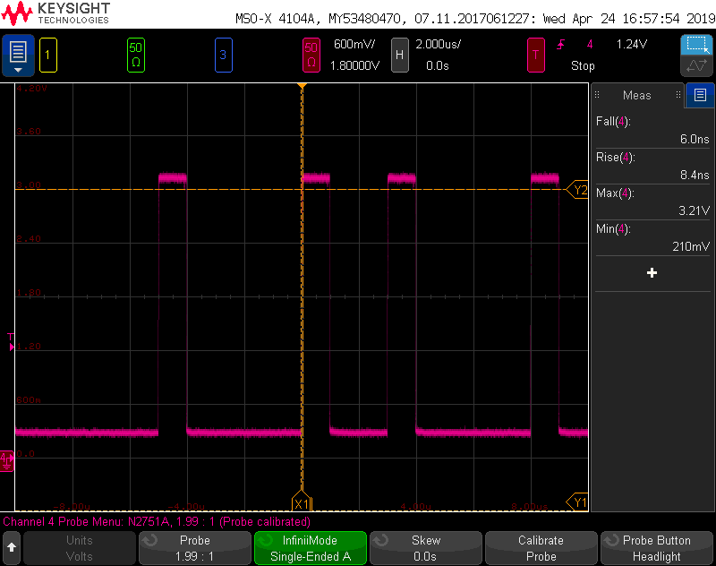
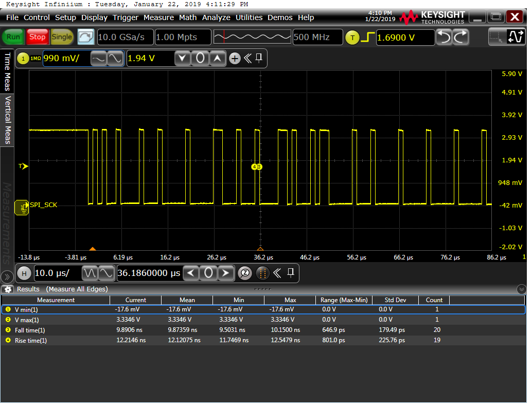
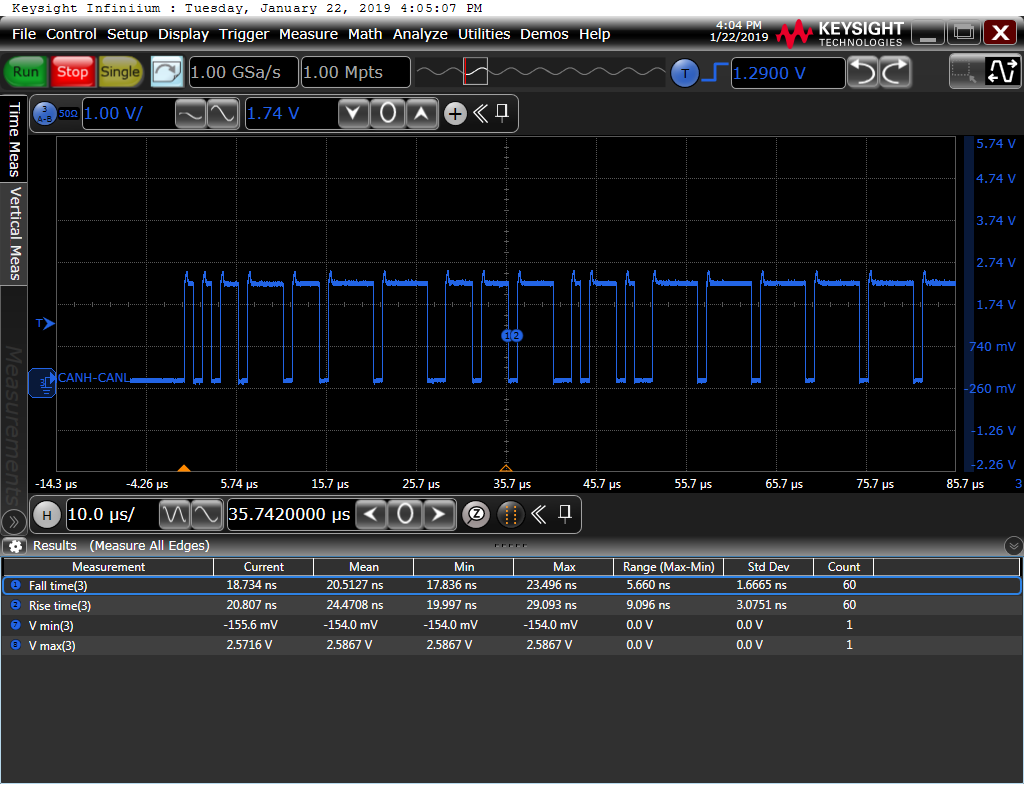
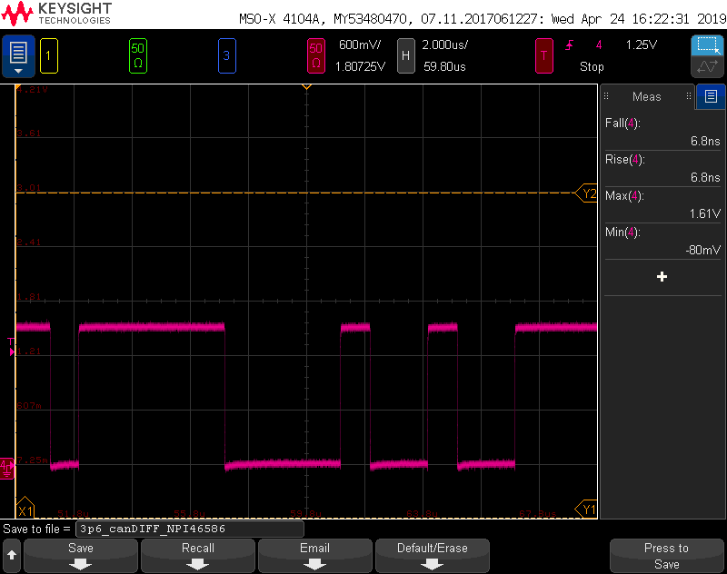
Datasheet states typical values for the RXD switching characteristics. I specifically interested in the fall and rise times. What are the maximum and minimum values?

Thank you,

Karen

  • Hi Karen,

    I am still working on gathering the data for this request.   

    I will respond tomorrow morning Dallas time with the findings.  

    Thank you for your patience.  

    Best Regards,

    Max Megee

    TI Transceiver Applications

  • Max,

    Thank you! Just following up to see if you need any information from me.

    Regards,

    Karen

  • Karen,

    The RXD output timing, as defined by the data sheet load (CL_RXD = 15pF), is as follows.  I gathered this based upon our characterization data on the device.  We usually provide typical values on timing parameters like the RXD output pin since the capacitor loading is not defined, although it is usually small.

    t_R: min = 5.5ns     typ = 7ns     max = 8.0ns

    t_F: min = 4.6ns   typ = 6ns     max = 7.0ns

    Let me know if you need anything further!  

    Best Regards,

    Max

  • Max,

    Scope capture with a differential probe as a single ended measurement (see attached) shows a rise time of 8.4ns. Should I be concerned with the CAN bus based on your max specs?

    Cl for the diff probe is significantly less then 15pF. Anything else I can try to ensure no issues on this bus?

    Thank you,

    Karen

  • Hi Karen,

    Thanks for the follow up.  I wouldn't be concerned here.  This is one of the reasons why rise/fall time on RXD is difficult to spec with a hard maximum limit.  It is difficult to quantify the capacitance that is introduced to the measurement, even though your scope is <15pF.  Any capacitance on board could be adding to this behavior, and that is expected for a real world system.  I wouldn't be concerned about the integrity of the CAN bus communication.  

    How fast are you operating?  It looks like you are transmitting multiple dominants with a single recessive bit in between, which would rightly give a worst-case rise time value for your specific system.  If you are transmitting a different bit pattern on the bus, let me know.  

    One thing to keep in mind is how the CAN protocol is decoding the bits on the RXD line.  The CAN protocol will set a sample point at some mid-way point during the bit, usually between 65-80% of the bit time.  And the maximum speed of the TCAN337 device is 5Mbps.  That gives a bit time of 200ns at the smallest.  By moving the sample point to somewhere between 65 and 80 percent of the bit time, the protocol controller should be able to safely sample the bit on the RXD line without issue.  And if you are running at speeds less that 5Mbps, then the margin only grows.  

    Does that make sense?  Do you have an expectation of adding significant capacitance to the RXD line in your system that would cause the rise/fall time to shift and call the bit-decoding reliability into question?  

    What is your application for the device, and what operating speed to you expect to run on the CAN bus?

    Best Regards,

    Max Megee

  • Max,

    Thank you for the quick response!

    I apologize for my delay as I was waiting for SW feedback.

    SW says that the CAN bus is operating a 1Mbit with approximately 50% overhead. I am not an expert on CAN bus so I am not sure of the pattern. These captures were taken with the passive probe rate between (10pF-25pF). 

    However, below are some scope captures of the CAN diff pair, RXD, and TXD (ignore the SPI_SCK label shown in error during capture). There appears to be a peak on the differential signal which I believe should not cause concerns based on the description of how the CAN protocol works. Correct? 

    Appreciate your input.

    Thank you,

    Karen

    RXD

    TXD

    CAN_DIFF

    CAN_DIFF with Diff probes

  • Hi Karen,

    These waveforms look like clean CAN communication to me!  It is a bit interesting that you see the CANDIFF peak on every dominant bit, but it looks like you aren't seeing the peak when you measure with diff-probes, right? I wouldn't be too worried about it.  It is more of a curiosity as to why you see the peak with certain probes and not with others.  It may be an inherent  response of your passive probe setup.  Let me know if I have read the scope shots wrongly.  But yes, it should have no effect on the integrity of the CAN bus communication.  

    Best Regards,

    Max