Hello,
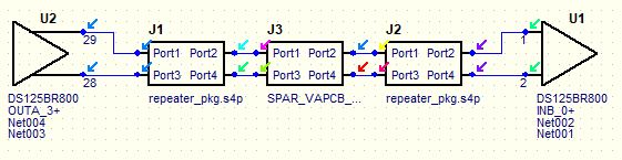
I am simulating the DS125BR800 redriver IBIS-AMI Model in a 8 Gbps setup using HSpice.
While I got the AMI models running, simply assining them to port-elements in HSpice, I have problems using the IBIS-part of the model for the RX-input in order to calculate a realistic impulse response.
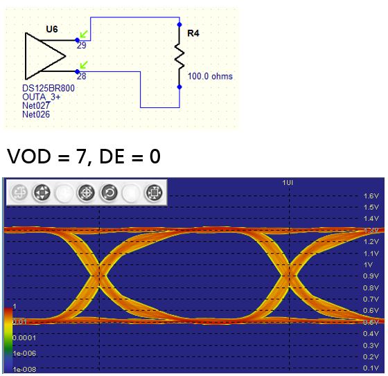
Due to the datasheet we have 50-Ω termination resistors connecting INA_n+/- to VDD and a Signal detection level at 180 mVp-p.
But if I have a look into the "DS125BR800_ramp.ibs" file at "[model] RX_IN" I am missing rising/falling waveforms which could describe its input impedance. Further there are the voltage levels defined as Vinl = 0.8 and Vinh = 2.
Is the model incomplete/wrong regarding the RX part? If I simulate my signal path with just the behavioral AMI, but without the RX-IBIS model, is it sufficient to simply assign two 50 ohms termination resistors?
Kind regards,
Jakob