This thread has been locked.

If you have a related question, please click the "Ask a related question" button in the top right corner. The newly created question will be automatically linked to this question.

low amplitude signal transmission

Other Parts Discussed in Thread: TLV9062, INA826

Hi,

Need help to understand what is the best way to transmit signal in the range of 250 to 500 mV ( Pulse ) over a cable to a distance of 25 mtrs without degrading the signal? The frequency of the signal may range from 1 kHz to 5 K Hz.

Will converting the signal in voltage form to current help to address the issue?

Regards

Kiran

  • The cable loses in the KHz range should be quite low.  There should be little attenuation for signals in this frequency range.

    Regards,

    Lee

  • Lee Sledjeski,

    Greetings and thanks for the reply

    will this mean the signal can be transmitted as is on a low noise cable?

    Can you suggest some  notes / write up which I can refer to?

    Regards

    Kiran

  • Kiran,

    Do you have a cable in mind? I prefer shielded twisted pair. Noise and electrostatic discharge (ESD) are some other concerns. Is the intelligence (data) in the amplitude or the frequency. If amplitude, how much error is allowed before the signal would be considered degraded?
  • Ron Michallick ,

    Greetings !!

    1) I am still in the process of zeroing on a cable. However, I had also thought of low noise shielded twisted pair.

    2) the intelligence is in the amplitude

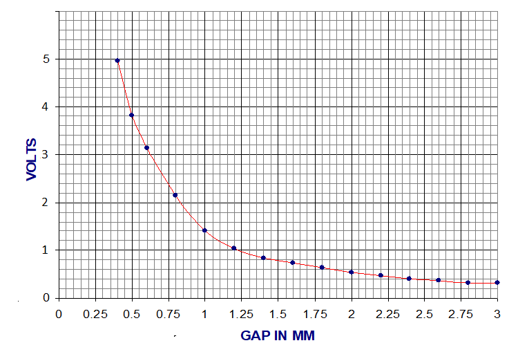
    3) the relation between change in amplitude Vs Gap is  non linear (rectangular hyperbola). I am not sure of a number at this point in time. May be any value between 2% to 3%  would be OK.

    Regards

    Kiran

  • Kiran,

    So a remote sensor. Is this sensor power also powered by the cable? Can I treat the sensor voltage as floating or do I have to offset the voltage to send differentially?
  • Ron Michallick,

    Greetings !! and thanks for the reply.

    1) The second and third part of the question is not  Clear.

    2) The following is the  configurations I have thought of :

    1. Have a ground station comprising of Power supply and  Conditioner electronics  at a distance of 2mts from the Sensor.
    2. Sensor excitation voltage  (150-200V) will be supplied from the ground station
    3. . The conditioned signal from the ground station has to be transmitted to a distance of 25mts..

    Regards

    Kiran

  • Kiran,

    If the 'ground station' and the 25 meter away station are both smart, processor controlled, then RS485 has great interface chips with outstanding ESD protection. 25m is just a short hop away.

    For analog transmission on twisted pair. Choose accurate (low offset voltage) amplifier to create a difference single center around a common mode voltage (1/2 of VCC is best dynamic range). On far end a difference amplifier can make the signal ended voltage again. Instrument amplifiers are the best bet here. You will need a add ESD protection; diodes, caps and resistors.

    Your transmit as a current idea also works for an loglog transmission. ESD protection is needed here too.

    Which of these ideas, sounds best?

  • Ron Michallick

    Thank you very  for the advices

    1) Processor controlled RS485 sounds the best. However, for me, adapting this technique requires additional work and more time at this point in time  Planning to  quickly try the first  prototype and then upgrade in the feature versions,

    2) I have no experience  doing such work. Hence, unable to zero on one method

    3) Converting single ended signal to differential and amplifying using an instrumentation amplifier sound good. Please correct if wrong.

    4) Can you please share a sample circuit / notes if any   which includes ESD protection ?

    Regards

  • Kiran,

    Here is a starting circuit. Feel free to replace TLV9062 with a lower input offset error op amp if needed. Basic ESD protection added.

    TLV9062 1-2.TSC

    Here is a circuit with just INA826. However this is not my device so I don't know how well it will drive cables. Post a new thread with INA826 as part number to get advice on that.

    INA 1-2.TSC

  • Ron Michallick

    Greetings and thanks for the reply !!

    What I understand from the circuit is is 2 opamps (TLV9062) are used to convert the single ended signal to differential and an INA (INA826) is used at the receiver end to covert the signal back to single ended. Please correct if I'm wrong.

    Cant I use a readily available Fully differential amplifiers for this purpose? If yes what are the parameters to be considered for selecting a FDA?

    Regards

    Kiran

  • Ron Michallick,

    Greetings and thanks for the reply,

    1) the signal I want to transmit on a twisted pair is a pulse (1 kHz -8 kHz) and is bipolar.

    2) For my application I prefer to use dual supply opamp (+/-5V), ( though consumes extra power)

    3) ESD and Noise protections are necessary

    4) You have suggested 3 solutions. which scheme of the three I should prefer and why?

    5) what is the error in the amplitude I can expect ( is it within 2 to 3%) ?

    Regards

    Kiran

  • Kiran,

    For +/-5V supply , I changed this circuit. INA826 is very accurate and should easily get your under 2%.  INA826 is not of of my groups devices so start a new post  with for the INA826 device and attach this circuit. Someone well acquainted with the INA826 will reply

    INA826.TSC

  • Ron Michallick ,

    Greetings and Thanks for he reply! !!

    Your guidance is very valuable.

    Will open a new post as suggested. How can we arrive at the figures of 2% accuracy?

    Should I rule out the option of using a Fully differential amplifier ? If yes, why ?

  • Kiran,

    FDA are usually used for high frequency applications opposed to high accuracy applications.