This thread has been locked.

If you have a related question, please click the "Ask a related question" button in the top right corner. The newly created question will be automatically linked to this question.

SN65LVDS84A: SN65LVDS84AQDGG:The chip is very easy to be damaged during hot plugging. Is there any solution?

Part Number: SN65LVDS84A
Other Parts Discussed in Thread: TPD2E001

Dear Pros,

1.Application:

"The LCD screen is separated from the host, and an SN65LVDS84AQDGG chip is used on the host side for output to the interface. The length of the outer cable (twisted pair with shielding) is less than 1 meter, and the other end is connected to the display module."

What's wrong with that? Any doubts or recommendations?

We have done some experiments, and now it is confirmed that this chip is very easy to be damaged during hot plugging. Is there any solution for consultation?We have tried to add 4 TPD2E001 TVS to 4 sets of differential signals, which will still be damaged.

The LCD signal switching chip of RGB to LVDS, SN65LVDS84AQDGG, has been damaged quite a lot recently, including 6 pieces in dozens of sets.

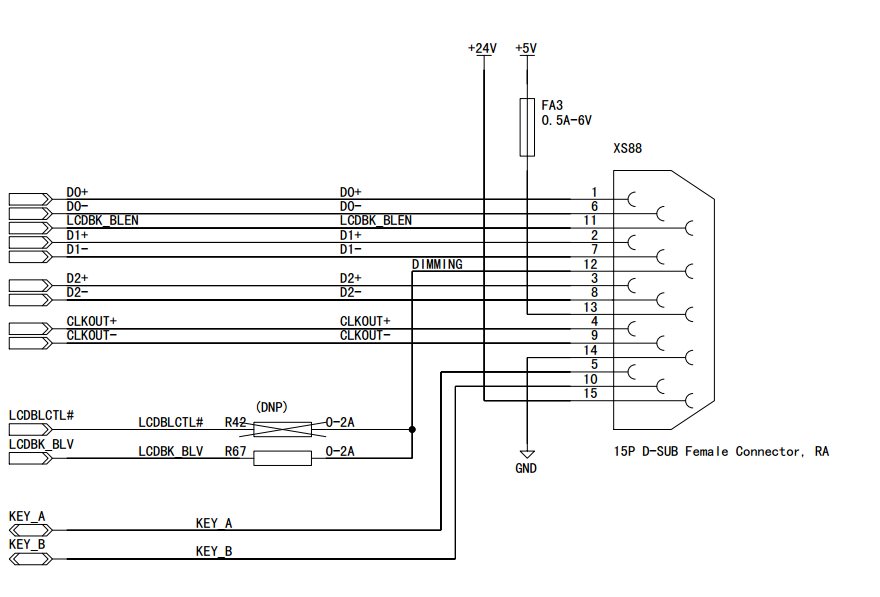
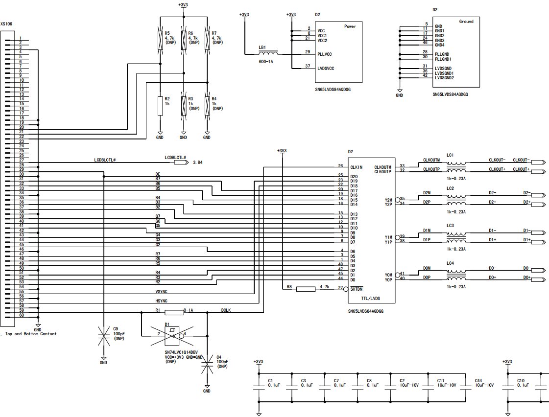
2.The circuit part is very simple, please refer to the attached picture.

The broken chip is basically due to abnormal impedance between LVDS differential pairs. For example, the resistance between Y0M/Y0P may be more than 10 ohms, several hundred ohms, or several megabytes.Resistance to earth is also small and large, ranging from more than 10 ohms to megohm.

Try replacing the common-mode inductor with a 10 ohm resistor, and then add TPD2E001DZDR, 4 pieces, and it still doesn't work. 
  • Hello Cris,

    We will need a few days to investigate this issue and return to you. We will plan to respond by 8/5 at the latest

    Best Regards,

    Casey 

  • Hi Cris,

    1) Is the SN65LVDS84 powered when you hot plug the D-SUB?

    2) Have you tried removing LC1-4?

    3) Does the D-SUB connect ground first? Try tying a separate ground between the cable and D-SUB and see if the damaging stops.

    Regards,

    Darryl

  • Hi Darry,

    1. Power on SN65LVDS84 when hot-plugging;

    2. We used 2 0 ohm resistors to replace lc1-4, but later changed to 10 ohm resistors, which will be damaged during hot plugging;No common mode inductance welding;

    3. We have tried to add a single line to GND in d-sub signal, that is, when hot-plugging and unplugging, both sides of the equipment are in the same ground, so it will not be damaged.However, the 24V/GND on the LCD side is powered by the system side, and there is no additional common ground connection in actual use.We can emphasize not to hot-plug, but once sent outside, offices, machine tool factories, sometimes there will be hot-plug.So I hope to try to change the circuit to solve the problem in the current situation.

    4.In addition, device damage occurs during the hot insertion of d-sub terminals, while no damage has been seen during the hot extraction.

  • Hello Cris

             Most probable cause for the issue you are observing are the transient ESD spikes that happens when you hot-plug. One way to solve this is to use TVS diodes (Transient Voltage Suppressors) which ensures that the transient voltage spikes dont go over what the SN65LVDS devices can tolerate

    Thanks

    Vijay

  • Hi Vijay,

    We have tried to add 4 TPD2E001 TVS to 4 sets of differential signals, which will still be damaged.

    The broken chip is basically due to abnormal impedance between LVDS differential pairs. For example, the resistance between Y0M/Y0P may be more than 10 ohms, several hundred ohms, or several megabytes.Resistance to earth is also small and large, ranging from more than 10 ohms to megohm.

    Try replacing the common-mode inductor with a 10 ohm resistor, and then add TPD2E001DZDR, 4 pieces, and it still doesn't work。

    Some suggestions?

  • Hello

          You mention , 'the broken chip is due to abnormal impedance'. Based on what you described, it seems, the IC got damaged first and because of the damage it reads abnormal impedance. It looks to me that one or both of the ESD diodes internal to the device are getting shorted to either supply or ground and the effect of that is possibly what you are seeing based on the measurements. Can you explain where you added the TVS diodes? On the chip side or on the connector side? I suggest adding TVS diodes on the coonnector side with the choke between the IC and the Connector. 

    Thanks

    Vijay

  • Hi Vijay,

    We added the TVS diodes  on the connector side。

    “it seems, the IC got damaged first and because of the damage it reads abnormal impedance”

    What might cause this problem?

  • Cris


         Both needs to be done. TVS diodes need to be added on the connector side but it is also important to have the choke in between as well. The device itself natively has some internal ESD protection. ESD protection internal to the device is primarily to support an HBM triggered ESD condition, primarily seen during handling. This assumes an ESD event stays on for a short interval and the internal ESD devices can turn ON and sink transient current and protect the IC for a short period of time. A hot-plug event , however causes voltage transients that lingers for significantly longer time that require special ESD protection schemes inside the IC. If an IC did not have the internal hot-plug supported ESD, then a hot plug event will cause a static event that lingers for quite a while damaging the ESD device (damage typically ends up as a short to power supply or ground or in some cases, an open) causing the behaviour with the impedance measurement you are seeing

    An external TVS diode may not help, since the internal ESD inside the IC may trigger first or the external TVS diode may not be able to sufficiently tamp down the voltage transient. This is where the CM choke helps a little bit and provide some isolation.

    Thanks

    Vijay