This thread has been locked.

If you have a related question, please click the "Ask a related question" button in the top right corner. The newly created question will be automatically linked to this question.

TLK10232: TLK10232

Part Number: TLK10232

Hi,

My colleague has posted a question about error code with TLK10232 last week and this problem has been transfered to me now. Our group still have no idea on how to solve this problem.

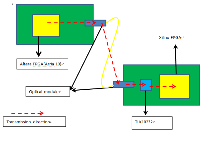
We are now using the altera FPGA sending data to an xilinx FPGA through optical module and TLK10232. The Intel FPGA send the data to 10G optical module through KR, and then the other board's optical module receives data and send it to TLK10232, lastly TLK10232 send it to the Xilinx FPGA. While error code occurs at the recieving part and can be detected on the Xilinx FPGA.

Moreover, during the test last week we find the error code might be related with temperature as the error code would become less while the board has been powered up for a period. We are looking forward to any suggestion to optimize our design and solve this problem.

Thank you very much.

  • Hi,

    My initial recommendation here would be to try to isolate exact location of the errors (Altera Rx vs Xilinx Rx vs optical module vs TLK10232) by enabling PRBS generation and checking at different test points of the link. The TLK10232 has both PRBS generation and verification functions that may be enabled by the user.

    Beyond this, it would be helpful for me to see a detailed block diagram for the test application in question. I'm having difficulty visualizing exactly how everything links up based on your initial high-level description.

    Cordially,

    Rodrigo Natal

    HSSC Applications Engineer

  • Hi, 

    I've drawn a simplified block diagram to show you the connection of our board and the signal direction. The error code occurs at the board with Xilinx FPGA. We have already checked that the signal sent from Altera board is correct. It might take some times to figure out where exactly the error code occurs. However, it should be occurs at either the optical module to the TLK10232 or TLK10232 to the Xilinx FPGA.

    Thanks.

  • Hi,

    You may refer to Section 3 of the TI application note per link below, "Setting up Tests and Measuring BER". At this point I feel it is critical to determine location of errors.

    http://www.ti.com/lit/an/slla351a/slla351a.pdf

    A couple of points:

    • If KR test pattern PRBS test pattern is generated from the PCS layer of the TLK SerDes:
      • If errors are still observed at Xilinx Rx then we know the problem is on the TI Tx to Xilinx Rx link
        • For this case, the customer may refer to Section 4.1 (transmitter side) of the TI application note per the link above for TLK Tx parameters that may be adjusted for link optimization
      • If errors go away, then we can deduce that the errors are happening on somewhere on link between optical module and TLK Rx
        • For this case, the customer may refer to Section 4.2 (Receiver side) of the TI application note per the link above for TLK Rx parameters that may be adjusted for link optimization

    Cordially,

    Rodrigo Natal

    HSSC Applications Engineer

  • Hi Natal,

    We have followed your advice and found out the explicit location that the error occurs. The error is observed at the Altera FPGA to TLK Rx. According to the references note, we have substituted the 'HS_SERDES_CONTROL_3' register'sdefault  value 1500  with 9800. After this change, error code becomes less than before. We usually capture the error code at the beginning  few seconds when power up the system. Now it could works approximately 10-15 minites without error code. Thank you for your advice.

    I've also uploaded the register's infomation at the attachment. However, the error code still can be observed after 15 minites. Thus I want to ask you to see if you have any experience about relavant registers could affect this situation or any value better than 9800 for substitution.

    Regards.

  • Hi,

    The adjustments you made affect the TLK precursor EQ. In theory the amount of TLK chip Rx postcursor ISI compensation is handled by the device’s adaptive DFE (Decision Feedback Equalizer) and needs no user configuration. In practice the quality of the DFE result is affected by the Tx link partner settings. I would recommend to sweep both the Tx output amplitude and Tx post-cursor de-emphasis for the Altera FPGA and see what settings translate to best error rate at TLK input.

    Cordially,

    Rodrigo Natal

    HSSC Applications Engineer