


Hi
I read the following articles to understand the operation of internal charge pump.
http://www.ti.com/lit/an/slva398a/slva398a.pdf
And I have some question about these article.
1. Regarding charge pump process (first article), that is explained as following.
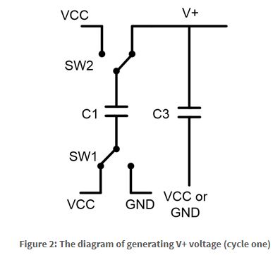
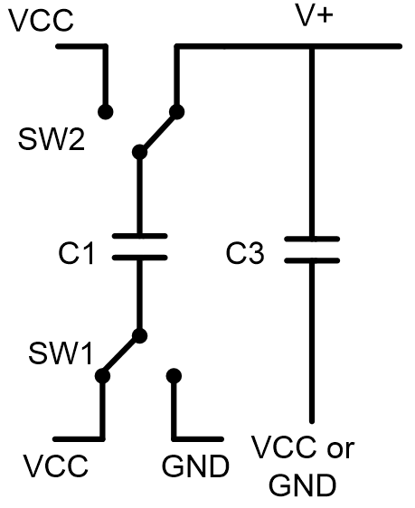
" In the first cycle, C1 charges to VCC (Figure 2)." But at Figure 2 , the connection of C1 is between VCC and V+.
I think that the first step(means "cycle one" is Figure 3. And second step is Figure 2. Is my understanding correct?
2.Regarding current spikes as it's mentioned at SLVA398A, the resister before flying cap can be reduced the current spike on flying cap. (mentions at section 4.2 Resister Selection)
So , can we add the resister around 10ohm if we find the current spikes at flying cap?

Best Regards,
Koji Hamamoto
