This thread has been locked.

If you have a related question, please click the "Ask a related question" button in the top right corner. The newly created question will be automatically linked to this question.

TPS65987D: questions for the boot mode setting

Part Number: TPS65987D
Other Parts Discussed in Thread: TPS65988, TPS65987, BQ25710

Customer is going to use TPS65987D in their notebook. They are asking for the boot mode pin setting. There are below 2 application cases they are considering:

1) TPS65987D port is configured as a DFP by default, with 5~20V, 0.9~3A sourcing capability; when the adapter is plugged, TPS65987D port switches to UFP, with 5~20V, 0.9~3A  sinking capability.

2) TPS65987D port is configured as a DFP by default, with 5V, 3A sourcing capability; when the adapter is plugged, TPS65987D port switches to UFP, with 5~20V, 0.9~3A  sinking capability.

As for Case 2, is it possible to achieve without EC controller?

For the above 2 cases, how to configure the ADCIN1 and ADCIN2 (need to support dead battery mode), respectively?  

Thank you.

  • Hi Aki,

    It is possible to achieve both cases without an EC. You can use an SPI Flash on the system instead and upload the exact configuration that you need for your application.

    Thank you,
    Eric

  • Eric,

    Could you please help further explain how to achieve this? What about ADCIN1 and ADCIN2? Could you please help suggest any reference materials ? Thank you!

  • Hi Eric,

    for case 1, it is a DRP application without  an EC. But  can't find  BUSPOWERZ Configurations  table with  5~20V, 0.9~3A sourcing capability in TPS65987 and TPS65988 SPI Less Host Programming Over I2C. Is it missing?

    for case 1, if DRP application with an EC for  5~20V, 0.9~3A sourcing capability. Is it possible to change the power level 5V/9V/12V/20V  by I2C(65987D informs EC and EC informs BQ25710 to change the power level)?

    Thanks.

  • Hello,

    There is no Pin strapping configuration to do 5V-20V sourcing. Either an SPI Flash or I2C host to load the configuration/patch would be required for that use case. 

    If there is an EC available and the power contract changes, the TPS65987D can send an I2C interrupt to the EC and the EC can read back the new power contract.

    Thank you,
    Eric

  • Hi eric,

    SLVA972A–May 2018–Revised April 2019  Table 1. BUSPOWERZ Configurations shows:

    Configuration5:
    DRP only

    But SLVSES1B –MAY 2018–REVISED JANUARY 2019  Table 7. Device Default Configurations shows:

    Configuration 5

    UFP only 

    1.Is it a mistake above?

    2.And for the simple configuration 5, TPS65987D works by the internal ROM, and the SPI Flash or SMBUS connection is not needed, right?

    3.Is there a configuration to support internal source and sink for DRP?

  • Hello,

    1. The correct version is in the device datasheet: http://www.ti.com/lit/ds/symlink/tps65987d.pdf

    2. That's correct, these are default ROM configurations. No external SPI or I2C connection is required.

    3. There is no ROM configuration to support DRP.

    Thank you,
    Eric

  • Hi eric,

    Thanks for your quick answer.

    Another question is how to ensure the UFP only support the 15V3A and 20V/3A sink capability  when I use the configuration 3 for TPS65987D?

  • Hello,

    This cannot be done with the default configurations. The default configurations that will sink between 5V-20V, like configuration 3, will accept all source offerings between 5V and 20V. You will need to have an external flash and external MCU to meet your specific requirement of only accepting 15V and 20V capabilities. 

    Thank you,
    Eric

  • Hi Eric,

    Currently, I try to boot up my PCBA for TPS65987D.

    Config as configuration 3( no SPI Flash or EC connection), ADCIN1 power level : 1.43V, but TYPEC only can sink 5V.   

    And I check the ohm value for CC1/CC2(65987 side) pin with GND, found both are 500K ohm, which are different with the EVM value around 40Mohm(65987 side) .  Is it abormal?

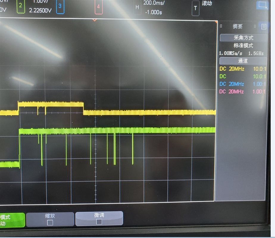
    The following picture is the CC waveform during boot up. Would you help to check them?

    Thanks a lot!

  • Hello,

    It appears you may have a hardware issue on your board. I would suggest comparing it to the EVM and see what is different in the schematics to help narrow down the problem. 

    Thank you,
    Eric

  • Hi Eric,

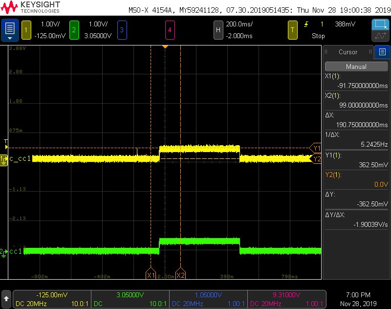
    Attach the CC1/C_CC1 PIN waveform when VBUS power up, why the CC1/C_CC1 only have around 362mv? any suggestion?

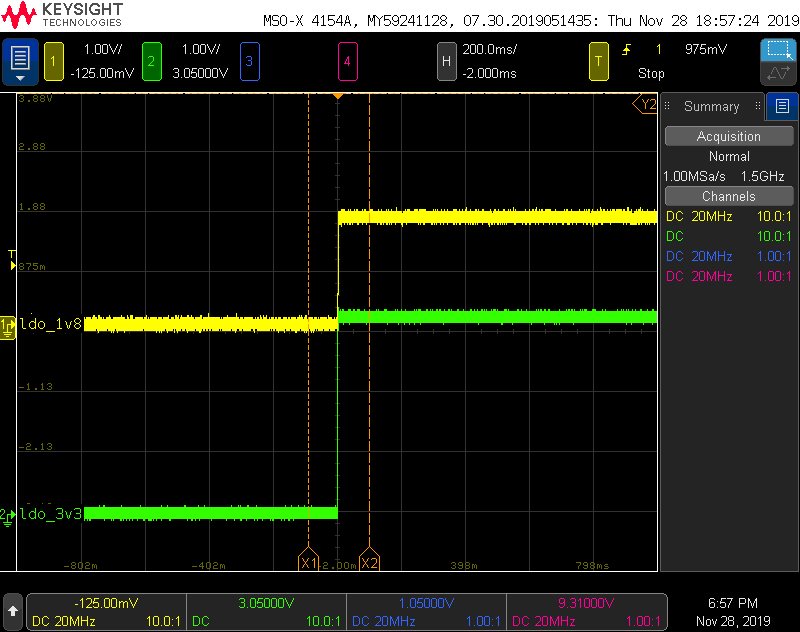
    and attach the LDO3V3 , LDO_1V8 power waveform for your reference:

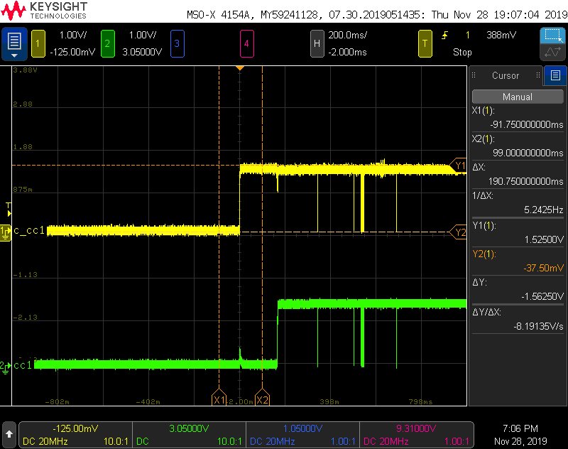
    also attach the EVM board C_CC1/CC1:

  • Hi Eric,

    I check the voltage threshold for EVM board, it seems it indicates the ufp dtetecting a source advertising 3A source capability, seems correct. But for my pcba voltage threold 362mv (seems VH_CCA_USB or VH_CCA_1P5),  are not meet my config( BP_NO wait,UFP, configuartion 3, MISO ground, ADCIN1 1.43V). 

    Thanks.

  • Hi Eric,

    Customer has solved the issue by changing the I2C address to 0x000b. Now it can support sink between 5V-20V with default configuration 3, and it could only support 5V sink before. However, they don't know why this change can help solve this issue. Could you please help explain it?  Thank you.

  • Hi Aki,

    It sounds like the customer may not be using 1% resistors or that the divider ratio is not centered in the ADCIN read range. I'm glad you were able to solve the issue.

    Thanks,
    Eric

  • Hi Eric,

    Customer said they met the same issue with our EVM, and also changed the I2C address to 0x000b to make the EVM support 20V sink. Could you please help check it? Thank you.