This thread has been locked.

If you have a related question, please click the "Ask a related question" button in the top right corner. The newly created question will be automatically linked to this question.

TCA9543A: I2C Problems

Part Number: TCA9543A
Other Parts Discussed in Thread: ISO1540

Hi All,

I am trying to talk to the TCA9543A I2C switch but having problems switching channels.

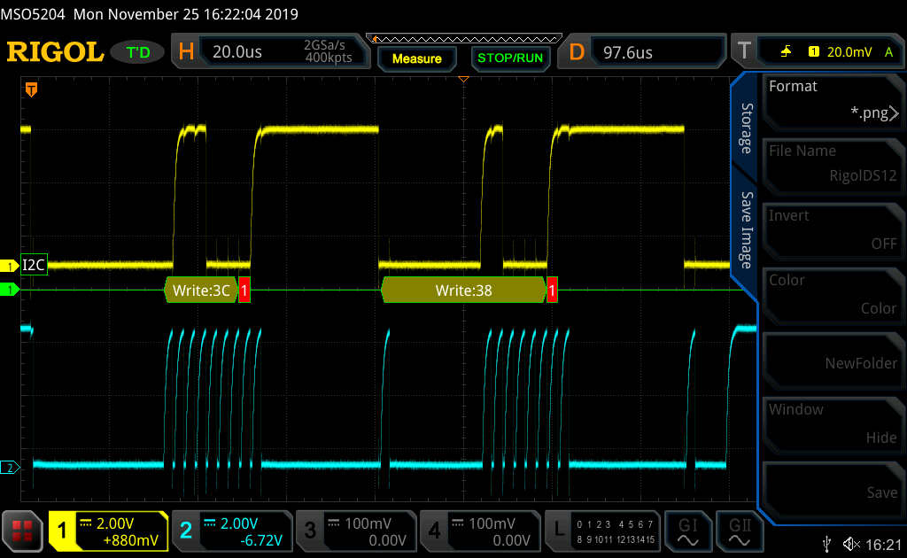
I have my micro up and running and the SCL line is running at 100kHz.  I can put a scope onto SDA and SCL lines going into the TCA9543A and SDA and SCL signals are going in,  but no data or clock come out of this chip on either channel 0 or channel 1.

The chip is configured so A0 and A1 are pulled to ground.  The Reset pin is pulled high.  Below is a snap shot of the commands i am sending the TCA9543A but nothing seems to make it switch.  Can somebody confirm i and sending the correct commands, or offer advice on what mistakes i am making.

I am guessing with the below commands sent to the TCA9543A i should get SCL output on channel 0?

	StartI2C(); // Send START condition
	IdleI2C(); // Wait for the end of the START condition
	WriteI2C(0x70 & 0xFE); // TCA9543A Slave address
	AckI2C(); // Wait for ACK
	WriteI2C(0x01); // Control register B0
	AckI2C(); // Wait for ACK
	StopI2C(); // Hang up, send STOP condition

Look forward to your input.

Thanks,

Rocketman46

  • Hello,

    Can you tell if you are getting ACKs from the switch in response to these commands?

    It is probably easiest to debug if we can take a look at the SDA and SCL waveforms received by the switch.  That way we know exactly what's going on at the hardware level. Could you please provide these?

    Regards,

    Max

  • Hi Max,

    Please see attached the screen shot of the I2C wave forms going into the TCA9543A from the micro.

    I do not really understand how i am sending in the psuedo code into the TCA9543A from the above post and the screen shot shows different numbers.  Also shouldn't the wave forms have a square leading edge and not rounded?  Can you spot any obvious mistakes.

    Look forward to your reply.

    Regards,

    Rocketman46

  • Hello Rocketman,

    It looks like the Microcontroller is getting Nacked on the 9th clock pulse (red '1' in I2C decode). This means that the TCA9543A either did not see the communication or there was an invalid input. This isn't surprising given that the information decoded by the scope does not show the correct address. The issue is likely with the setup or execution of the MCUs I2C implementation. Would you be able to share the function implementations you're calling to see if we can find out why the numbers in the parameter fields aren't showing up in the scope shots?

    Ideally this waveform should be square, but in a real system shapes like this are what we expect. Because I2C lines are driven by open-drain pull-downs, the falling edges are much quicker than the rising. Rising edge speed is influenced by the strength of the pull-up resistor on the bus and the capacitance of the bus. This is why you see the rounded edges at the top of the waveform while the falling edges are crisp. It's difficult to tell if this is an issue in your case with the zoomed-out scope shot. I presume not because the scope is able to decode some information. If you believe this is an issue, try zooming in more and making sure the data line does not transition while the clock is high (with the exception of the start and stop conditions).

    Regards,

    Eric

  • Hi Eric,

    Thanks for your help.

    I have made good progress, when removing the in series TCA9543A switch i can talk to the battery pack from the micro and receive battery voltage.  So this confirms the micro to battery code is correct.

    With the switch put back series i can write to the battery on both channels B0 and B1, and read this data on the scope, but i cannot receive data back from the batteries, though the switch to the micro.  Below is my code, can anybody see what i am doing wrong on my read section.

    Regards,

    Rocketman46

    // Write to battery
    
    IdleI2C();                       
    StartI2C();                      
    IdleI2C();                       
    WriteI2C(0xE0);                  // TCA9543A Slave address write
    IdleI2C();                       
    WriteI2C(0x01);                  // Control register B0
    IdleI2C();
    StopI2C();
    
    IdleI2C();                       
    StartI2C();
    IdleI2C();                       
    WriteI2C(0x16);                  // Send battery address and read bit
    IdleI2C();                       
    WriteI2C(0x09);                  // Send battery command to retrieve voltage 
    IdleI2C();                       
    StopI2C();                       
    
    //Read from battery
    
    RestartI2C();                   
    IdleI2C();                       
    WriteI2C(0xE1);                  // TCA9543A Slave address read
    IdleI2C();                       
    WriteI2C(0x01);                  // Control register B0
    NotAckI2C();
    StopI2C();
    
    RestartI2C();                    
    IdleI2C();
    WriteI2C(0x17);                  
    IdleI2C();                       
    lsb_battery_voltage = ReadI2C(); // Read first byte of data
    AckI2C();                       
    msb_battery_voltage = ReadI2C(); // Read nth byte of data
    NotAckI2C();                     
    StopI2C();                     

  • Hi,

    Any help would be gladly accepted as i am struggling to get this working, and i am under alot of pressure to get it finished.

    Thanks,

    Rocketman46

  • Hi,

    Here is the circuit i am trying to control with the above code.  Also note reset is pulled up by a 4.7k resistor.  

    Look forward to your reply.

    Rocketman46

  • Hi Rocketman,

    Thanks for the code and schematic. I'm glad to hear that you were able to make good progress. I think I can help you out with reading from the battery slave.

    I believe there is some confusion about I2C switch operation. I notice in your code that when you try to read from the battery, you first send a read command to the TCA9543A (line 25). I presume that this would be to verify the switch configuration, however, you do no save the response of TCA9543A and instead try to write to the control bit for B0 again (line 27). This would likely cause errors in the device as the slave is trying to respond over the data line while the master is also trying to write. I suspect this is where you are encountering the communication problem. 

    TCA9543A acts as a switch and only changes states when directly controlled by a master. During the first section of the code you posted in "Write to battery", you correctly configure the switch to enable channel B0 (line 3 through line 10). The following transaction between the master and the battery is not monitored by the switch because the address field did not match the device's address. Because the device is already configured to have channel B0 enabled, you would be able to immediately read from the battery without having to reconfigure the switch. This means the code from line 23 through line 29 is not necessary to communicate through the device. I also believe if this section was identical to the first configuration (line 3 through line 10) the communication would also succeed. 

    Let me know if this makes sense and if this resolves the problem. 

    Regards,

    Eric

  • Hi Eric,

    Thanks for your reply.  If i use the below code with the switch and optos removed and just communicate between the micro and one battery i have success, but when i add the above circuit back in, i cannot read from the batteries.  I have tried your tips but still no data back from the batteries.  I think i am lost in translation or something.

    Thanks,

    // Write to battery
    
    IdleI2C();                       
    StartI2C();
    IdleI2C();                       
    WriteI2C(0x16);                  // Send battery address and read bit
    IdleI2C();                       
    WriteI2C(0x09);                  // Send battery command to retrieve voltage 
    IdleI2C();                       
    StopI2C();                       
    
    //Read from battery
    
    RestartI2C();                    
    IdleI2C();
    WriteI2C(0x17);                  
    IdleI2C();                       
    lsb_battery_voltage = ReadI2C(); // Read first byte of data
    AckI2C();                       
    msb_battery_voltage = ReadI2C(); // Read nth byte of data
    NotAckI2C();                     
    StopI2C();

  • Hi Rocketman,

    Try the following code. Your configuration of TCA9543A is initially correct. This is why you can write to the battery. I believe there is an issue when you try to reconfigure the device before reading from the battery. Leave out the reconfiguration section and see if you can read successfully from the battery.

    1
    2
    3
    4
    5
    6
    7
    8
    9
    10
    11
    12
    13
    14
    15
    16
    17
    18
    19
    20
    21
    22
    23
    24
    25
    26
    27
    28
    29
    30
    31
    32
    33
    34
    35
    36
    37
    38
    39
    // Configure TCA9543A
    IdleI2C();                      
    StartI2C();                     
    IdleI2C();                      
    WriteI2C(0xE0);                  // TCA9543A Slave address write
    IdleI2C();                      
    WriteI2C(0x01);                  // Enable channel B0
    IdleI2C();
    StopI2C();
    // Write to battery
    IdleI2C();                      
    StartI2C();
    IdleI2C();                      
    WriteI2C(0x16);                  // Send battery address and read bit
    IdleI2C();                      
    WriteI2C(0x09);                  // Send battery command to retrieve voltage
    IdleI2C();                      
    StopI2C();                      
    //Read from battery
    RestartI2C();                   
    IdleI2C();
    WriteI2C(0x17);                 
    IdleI2C();                      
    lsb_battery_voltage = ReadI2C(); // Read first byte of data
    AckI2C();                      
    msb_battery_voltage = ReadI2C(); // Read nth byte of data
    NotAckI2C();                    
    StopI2C();
    // Continue with other battery communications....

    Regards,

    Eric

  • Morning Eric,

    I have tried your new code and this still does not work.  To give you more details of the battery management chip, i am using the TI 3060.  I am sending this chip I2C commands at 70kHz.

    I have just confirmed again it works correctly with the optos and TCA9543a switch removed.

    Let me know if you have any other ideas.

    Thanks,

    Rocketman46

  • Hi Rocketman,

    What is the full part number for the battery management chip you're using? It's possible that the IC cannot communicate through the ISO1540 due to the buffer's low-level input voltage requirement (0.5v). Cabling may also introduce some error here as side 1 of this device does not have as great of a pull-down strength as side 2.

    Could you share scope-shots of the communication before and after adding TCA9543A? I'm curious if after initializing the switch if communication is indeed going through. Could you test both sides of the switch after it's connected?

    Have you been able to see the expected values decoded from the scope? Using the setup with only the switch would be a good way to debug this because you now good data is being sent/received. 

    Regards,

    Eric

  • Hi Rocketman,

    Have you been able to make progress on you I2C communications? If you were able to find a solution I would like to know how you went about it.

    Regards,

    Eric

  • Hi Eric,

    Thanks for your help.

    I have now got the switch working.  At 100kHz the circuit, switch, optos and batteries wouldn't communicate, but when i dropped to 80kHz everything worked.  

    Many thanks again for your help.

    Rocketman46

  • Hi Rocketman,

    That's great to hear! I'm curious if the added propagation delay from the buffer crossed a system-level threshold. I'm glad you were able to find a solution! Thank you for sharing it with us.

    Regards,

    Eric