This thread has been locked.

If you have a related question, please click the "Ask a related question" button in the top right corner. The newly created question will be automatically linked to this question.

SN75DP130: HPD and AUX signals not propagating from SNK interface to SRC interface

Part Number: SN75DP130

Hi,

We have a custom board with Cyclone 10 GX FPGA and SN75DP130. FPGA has DP IP core instantiated in Tx mode (1 lane @ 5.4Gbps) on source path. Standard Dell monitor is used as the sink.
We are not programming any registers and relying on the auto link training to set the equalization and data rate. We could see the HPD_SNK from the monitor going high, but its is not reflecting on HPD_SRC output. Also no activity on AUX_SRC interface. The device is out of reset and responds to I2C read commands by returning non-zero values. These register values keep changing over time, so SN75DP130 is trying some thing.

Some of the Device Pin Connections:

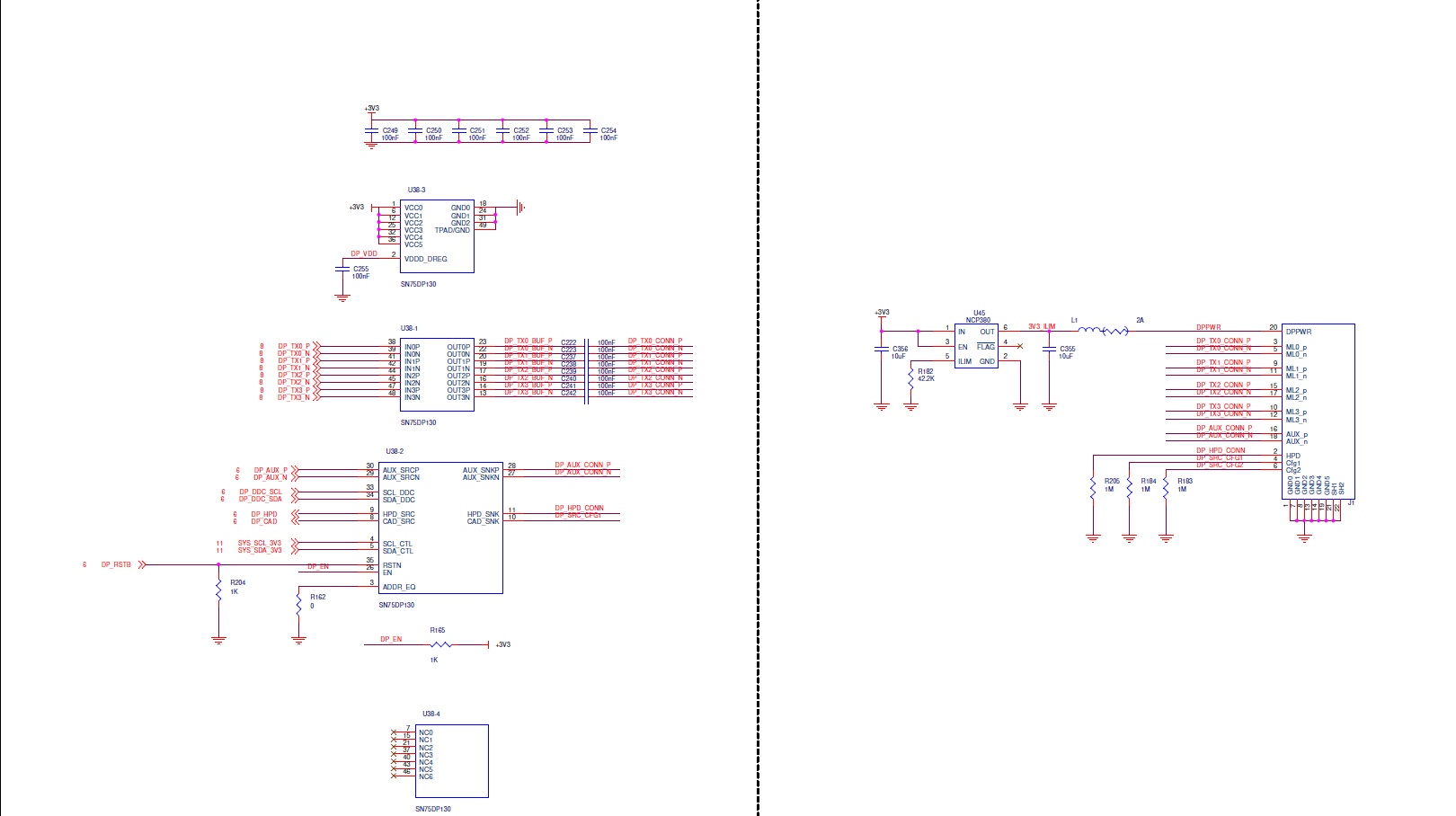
EN signal is connected to 3.3v supply through a 1K pull-up resistor.
CAD_SNK is connected to connected to cfg1 pin of DP Connector and has external 1M resistor to ground.

What could be blocking SN75DP130 from progagating HPD signal from SNK interface to SRC interface? Does the device propagate HPD signal only after successful link training?

Do we need to check any specific registers or device pins to understand the problem?

Thanks

  • Would you please send me the schematic for review? The device is out of reset and responds to I2C read commands by returning non-zero values. These register values keep changing over time, so SN75DP130 is trying some thing. -> The I2C registers should not constantly toggle.

    HPD needs to go high before link training can start. If HPD_SNK goes high, then HPD_SRC should also go high.

    Thanks

    David 

  • Thanks for your time. Please find the attached DP portion of the schematic.

  • 1. Please replace one of the +3V3 decoupling capacitors to 10uF

    2. Please change C255 to 1uF.

    3. Are the inputs being AC-coupled?

    4. Is the AUX being AC-coupled and have the proper pull-up/pull-down?

    5. Does the DDC have the pull-up resistors?

    6. Have you checked the power up timing between VCC and RSTn?

    Thanks

    David

  • Thanks for the suggestions.

    >>> 3. Are the inputs being AC-coupled?

    Only main link differential signals are AC coupled.

    >>> 4. Is the AUX being AC-coupled and have the proper pull-up/pull-down?

    On the SNK side, the signals are directly connected to the connector (no coupling/resistors).

    On the SRC side: AUX_SRC <--> M-LVDS Driver/Receiver (NB3N201S) <--> Voltage Level Translator (NLSV1T244) <--> FPGA

    >>> 5. Does the DDC have the pull-up resistors?

    We have 1.5K pull-up on both I2C interfaces.

    I will try replacing the caps and update how it goes.

  • Please make sure the input is AC coupled.

    AUX also needs to be AC coupled and if designed as a DP source, then 100k pulldown  on AUXp and 100k pullup to 3.3V on AUXn. If designed as a DP sink, then it needs 1M pullup to 3.3V on AUXp and 1M pulldown on AUXn. For eDP, the pullup/pulldown is optional.

    Thanks

    David