This thread has been locked.

If you have a related question, please click the "Ask a related question" button in the top right corner. The newly created question will be automatically linked to this question.

AM26LS32AC: how to calculate the Tc from Datasheet

Part Number: AM26LS32AC

Hi

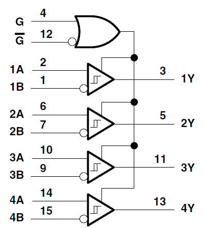
My customer want to calculate Tc of AM26LS32AC(Differential Receiver) from datasheet. 

The question is at the end. Let me explain the situation first.

■ Conditions
* The input voltage Vcc of the differential IC is 5.1V.
* Expected to be 95 ° C at maximum ambient temperature.
* The above temperature is the temperature when the differential signal is open and 2.73V and 2.37V are input to the differential terminal.

From the data sheet, we will calculate the allowable value of Tc as follows.

(1) Input power to differential IC: Icc × Vcc   ※ Icc and Vcc will be calculated at maximum values.
(2) Input power when differential signal is added: Ii(= differential input current) x Vi x 6 input terminals ※In consideration of margin, Ii is calculated not by pulse but by constant-on.

(3) {(1) + (2)} × 108 ℃ / W ※ Calculate by this method in order to take margin into account.

With the above background, please confirm the following items.

① Can the allowable temperature of Tc be calculated from the above
② Maximum value of Icc: I㏄_max = 70mA, is it correct?
③ Maximum value of Ii: Ii_max = 1.2mA, is it correct?
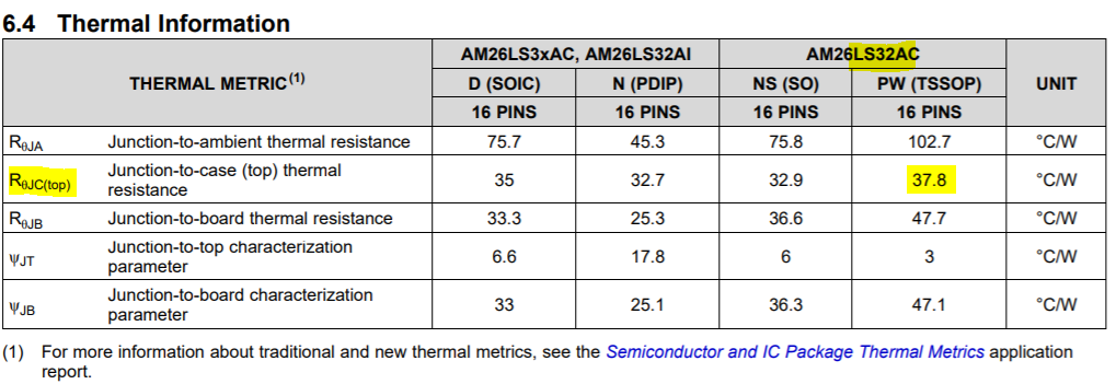
④ Thermal resistance: Rth_j-c (= thermal resistance between junction and case)  = 108 ℃ / W, is it correct?

------------------------------------------------------------------------------------------------------------------------------------------------------

In my own opinion, thermal resistance only shown in DS is Rth_j-a(= thermal resistance between junction and ambient) =108 ℃ / W.

But how can I get Rth_j-c from calculation?

Jo

  • Hi Jo,

    Thank you for the detailed post. I've reviewed the equations you shared and everything looks in order. As many of our datasheets do not specify every thermal specification of the device, being able to do these calculations based on the specified power dissipation and thermal characteristics is a good skill to adapt the information. 

    I am unable to find the information posted in your screenshot on the latest version of AM26LS32AC's datasheet. It also seems some of the values in the calculations above do not line up perfectly with the current datasheet. Please be sure you are using the latest information on TI.com for your calculations. Your reasoning and equations otherwise look good. 

    Let me know if you have any more questions regarding thermal characteristics or if you have trouble finding information on the latest datasheet. 

    Regards,
    Eric

  • Hi Eric

    Thanks for your kindly reply. I've got the latest datasheet now.

    Let me confirm two things as below noted ① and ②.

    I will use only 3 pairs of input. 

    ①Regarding ”Input power when differential signal is added”, 

       Since Ii is written "line input current" in datasheet, I think the total Ii for 1 pair of input will be multiplied by 2. 

       That's why I multiply by 6 in total. Am I correct?

     →(2) Input power when differential signal is added: Ii(= differential input current) x Vi x 6 input terminals ※In consideration of margin, Ii is calculated not by pulse but by constant-on.

    ②Since I can get Rth_j-c from the latest datasheet, i should use 37.8℃ / W but not 108℃ / W for calculation, am i correct?
     →(3) {(1) + (2)} × 108 ℃ / W ※ Calculate by this method in order to take margin into account.

    Regards, 
    Jo

  • Hi Jo,

    1) I think the total Ii for 1 pair of input will be multiplied by 2. 
    Yes, each pin will experience the specified input current. Note however that this value is specified at voltages outside normal operating conditions and actual current through this pins during typical use will be less. Typical RS-485 signals will also have each line be inverted causing one pin to sink less current than the other. For your calculations, it may be prudent to assume worst-case to ensure fault conditions are also taken into account and give you a wider margin for typical operation. 

    2) Since I can get Rth_j-c from the latest datasheet, i should use 37.8℃ / W
    Yes, the value for RthJC that pertains to the specific part number and package type can be used here. Because the conduction through the junction-to-case of the package can move heat more efficiently, this value is smaller than the junction-to-ambient thermal resistance. In reality, the device will dissipate heat both to the attached board and the ambient environment, so thermal relief will come from both of these values. For a rough approximation, you may only calculate the junction-to-case thermal resistance as this is where the majority of the device's heat will be transferred. 

    Regards,
    Eric

    [Edit]: formatting