This thread has been locked.

If you have a related question, please click the "Ask a related question" button in the top right corner. The newly created question will be automatically linked to this question.

TPS25810: No 5V from VBUS pin with a specific test fixture

Part Number: TPS25810

Hi,

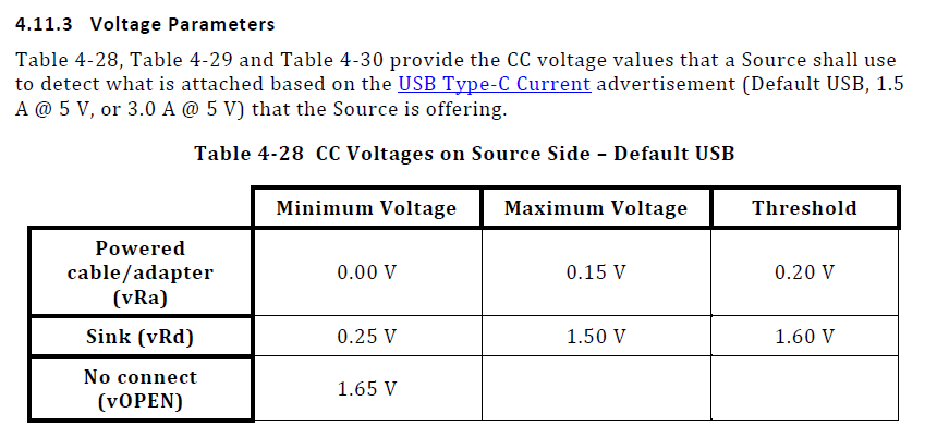
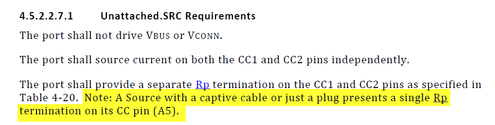
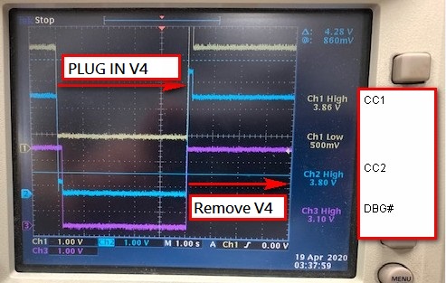
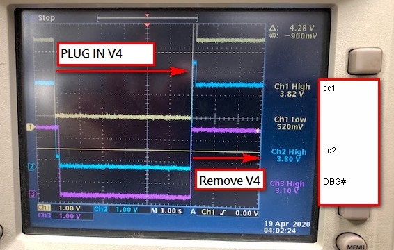
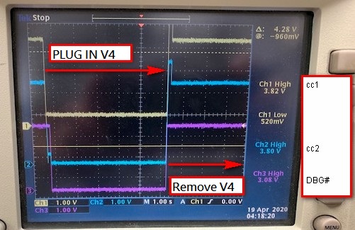
There's a specific type-c function fixture which is workable with other system (a DRP port), but not workable with the DFP port using TPS25810.  Please check below for VBUS/CC1/CC2 waveform at the moment when the fixture is plugged in and removed.  Please advice what we can check further to judge why there's not a valid 5V on VBUS when this fixture is connected.

Thanks!

Antony

Antony

  • Hey Antony,

    The TPS25810 can only be used as a Type-C Source DFP. So if you connect another Type-C Source DFP to the TPS25810, neither one of them will present an Rd on the CC lines so 5V will never be presented on VBUS

  • HI Adam,

    TPS25810 is currently implemented as a DFP only port at a host system, and the plug-in fixture is a DRP device.  Do you mean TPS25810 can support this DRP fixture??

    In parallel, the Rp within TPS25810 should always be valid, right?

    Thanks!

    Antony

  • Hi Antony,

    If the DRP fixture is not presenting an Rd, then the TPS25810 will not close its switch and present 5V on VBUS

  • Hi Adam,

    Based on the waveform provided earlier which is measured at TPS25810 side, can we judge if there's a valid Rd from the fixture from it?  Or we need to measure CC1/CC2 at fixture side to clarify this?

    Thanks!

    Antony

  • Hi Antony,

    Looking through the Type-C spec, what I believe could be happening is that the DRP device is pulling the CC levels below a detectable level for the TPS25810. Below is an excerpt from the Type-C spec stating the voltages that the source use to detect if a sink device has been connected. This is for a default USB device, which has the lowest minimum voltage level of 250mV.

    It is difficult to see on the oscilloscope (2V per division) so if the voltage on CC1 is close to or below 250mV, the TPS25810 may not be detecting it

    One thing you could try is have the TPS25810 advertise 3A current capabilities, which will present the lowest Rp resistor value, which should bring the detected voltage on CC1 up.

    Section 8.2.1.3 of the data sheet show application curves of the TPS25810 which may help serve as a reference point of what expected behavior should look like

  • HI Adam,

    After further checking with the customer, this fixture has a captive cable with male type-c connector plug connected to the type-c receptacle connector at the host system using TPS25810.  When this fixture acts as a UFP role, it would presents Rd on both CC signals.  This seems not aligned with my understanding of UFP device with captive cable.  So, for such special device, how would TPS25810 interacts with it?

    THanks!

    Antony

  • Hi Antony,

    Yes, a captive cable should only present a Rd on one CC lines. However, I still do not believe that this is the cause and believe that this issue is from the cable pulling the CC voltage below the minimum threshold

  • Hi Adam,

    After cross checking with the customer, the fixture actually behaves as a debug accessory defined in type-c standard.  Here's the comments from the customer side:

    The TPS25810 is not on a system with a captive cable. The fixture has the captive cable in this scenario. The note that TI highlighted does not apply to the TPS25810 side; it is in the Unattached.SRC state, but it does not have a captive cable. Also they present Rp on both CC lines anyway so they should know that it does not apply.


    Fixture is in the "B.2.4.1.2.1 UnattachedDeb.SNK Requirements" state, which says that Fixture should follow: "Both CC pins shall be independently terminated to ground through Rd."


    Furthermore, for TPS25810 to exit Unattached.SRC state (see 4.5.2.2.7.2 Exiting from Unattached.SRC State), it requires "The SRC.Rd state is present on either the CC1 or CC2 pin ..." not only CC1 or CC2. So both CC1 and CC2 should trigger this exit condition.


    Then the source side (TPS25810 side) gets to the following statement in 4.5.2.2.8.2 Exiting from AttachWait.SRC State:

    "If the port supports Debug Accessory Mode, it shall transition to UnorientedDebugAccessory.SRC when V BUS is at vSafe0V and the SRC.Rd state is detected on both the CC1 and CC2 pins for at least tCCDebounce."


    which then leads the TPD25810 side to the following in 4.5.2.2.17.1 UnorientedDebugAccessory.SRC Requirements:

    "The port shall supply V BUS current at the level it advertises on Rp. The port shall not drive V CONN ."


    In short, Fixture is operating correctly as a DTS DRP (or DTS Sink); see appendix B: "Debug Accessory Mode"


    Customer also measure VBUS/CC1/CC2/DEBUG pin of TPS25810 when CHG_HI and CHG are configure at different levels as below showing the moment when the fixture is removed and then inserted.  It looks to me we didn't detect it as a valid debug accessory?  Please let us know if you think TPS25810 behaves correctly or not and why.  THanks!

    Photo2:

    CHG : L  CHG_HI : L


    Photo1:

    CHG : H  CHG_HI : L


    Photo3:

    CHG : L  CHG_HI : H

    Photo4:

    CHG : H CHG_HI : H

    Antony


  • Hi there,

    The cc voltages in the previous thread were not correct because of the wrong connection of Servo V4. That made the Servo V4 a DFP role instead.

    Some updates for the scope pictures. We can observe 0.4V on the cc1 line. 0V on the cc2 line no matter what the current capability settings are as my team and I thought both cc lines should be pulled up by the DFP side. However, the DEBUG# gpio stays low in all current broadcast cases.

    Case 1:

    Photo_1/ CHG:H/ CHG_HI:L


    Case 2:

    Photo_2/ CHG:L/ CHG_HI:L

    Case 3:

    Photo_3/ CHG:L/ CHG_HI:H

    Case 4:

    Photo_4/ CHG:H/ CHG_HI:H

    How can we let TPS25810 pull up both cc lines in this circumstance. Any thoughts?

    Ryan

  • Hello Ryan,

    Thank you for the clarification. Looking at the new measurements, it looks like the cable has an internal Ra and is pulling down CC2. The TPS25810 is presenting a pullup on both CC pins as you can see the positive voltage on both channels when the device is removed.

    If you look at the table I shared earlier, an Ra resistor can pull down the CC voltage to 0V which is likely what you are seeing

  • Hello Adam,

    Thanks for the reply. As the threads updated on April 24th, the USB-C fixture(Servo V4) has a captive cable.

    The connection will not be like the standard DFP-to-UFP connection as the shown picture. We do not need to detect cable orientation either.

    Plus, the block diagram you presented. Two cc pins both have a pull up Rp to a voltage source on the DFP end. They should permanently present pull up voltage anyway.

    When Servo V4 works in debug accessory mode as the USB-C standard, both cc lines on the captive cable end present Rd. 

    When the two devices connect, the cc lines are expected to see the same level of voltages. However, they are at different voltage levels.

    Servo V4 does not reply on VBUS to work. But it requires to know if the debug mode is enabled through the two cc lines. My question is, why TPS25810 pulls up only one cc line in such a case?

    Cheers,

    Ryan

  • HI Ryan,

    The TPS25810 is presenting a pullup on both CC pins, that is why I shared the capture from the spec. You can see the TPS25810 present a voltage on both CC pins before and after the connection, but when the device is connected, the CC signal is pulled low. The only way that a voltage would not be measured on either CC pin is if there is a strong enough pull down connected to the CC channel.