This thread has been locked.

If you have a related question, please click the "Ask a related question" button in the top right corner. The newly created question will be automatically linked to this question.

DP83822I: Question about Auto-MDIX negotiation

Part Number: DP83822I

Hello,

I got a question about the auto MDIX negotiation: 

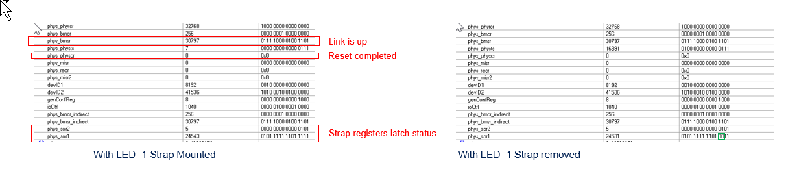
In the system I am working with the PHYS DP83822I  is strapped in default mode with floating RX_ER  --> AMDI_EN=1.

Now I expect that  in this condition register PHYCR (0x19) bit 15 to be set.

What I see is that register 19 is all zero. Is that correct?

the prototype I'm working with is  directly connected to my PC with a straight cable   and it can communicate. What am I missing?

Another question.

For layout reasons we might need to swap TDP-TDM with RDP-RDM from the phys to the connector. This would result in the phys to treat the straight cable as a twisted one and vice versa. Can you see issues for this unconventional solution?

Best regards,


GZ

  • Hi GZ,

    Can you provide the register values for 0x0467 and 0x0468? This will verify what value is being latching into PHY via the straps?

    Swapping TD and RD channels will not cause ill effects. Register 0x000B[5] indicates which channel is used as RX and TX. 

    Regards,
    Justin 

  • Thank you Justin,

     was planning to write the code necessary to grant the access to the extended registers. You will get the results on next week.

    Have a nice weekend.

    G.

  • Ciao Justin,

    Please find in attach the  resulting reading of some important registers amongst which  SOR1 and SOR2. The device (in out prototype) is working without external bootstraps in default mode.

    What I find strange is that registers DOR1 and SOR2 show discrepancies with the expected strap configuration, and that should impact on the expected phys address which is actually in line  with what we are expecting. There are for sure layout problems so we cannot go past 10Mbps and it seems that the auto negotiation bit never sets.

    Can you please give me your insight about that?

    Best regards,

    G.

  • Hello,

    I do not believe that you are properly implementing the extended register read operation. SOR1 and SOR2 should not read the exact same value but is common if the extended register read operation is not followed. 

    The strap configuration you shown in SOR1 will not advertise 100Base-TX, which explains why you are only able to link to 10Mbps. Further evidence the SOR2 register is incorrect is 0x0468[3:0]=1111 would change the PHY address from default to 12, which does not appear to be the case. 

    For the remaining registers, 0x0461 is correctly reading the default value, the expected value you have listed is incorrect unless you have programmed the PHY as such. 

    Regards,
    Justin 

  • Ciao Justin,

    My bad, there was a typo in the define concerning SOR2 register. Now we got the correct reading.

    The lower table ( the one with SOR1 and SOR2 registers) implements several indirect readings I exploited in order to be reasonably sure that

    what I was watching concerningSOR1 and SOR2 is their content. The other indirect readings make sense so I believe that the code I wrote (according to the devices; datasheet paragraph 8.4.2.1) is correct.

    Please let me know your opinion

    regards,

    G.

  • ciao Justin ,

    Please find in attach the portion of schematic concerning the Ethernet. As you can see, by removing the strap on LED_0 the device is working with straps in default mode.  I also got one regret with the bead connected with the between the filter capacitors of VDD3 and DGND. I believe this is misplaced: the only effect of this inductor is to counter the capacitor's filtering effect, lifting the capacitors from gnd at frequencies past the series resonance.

    Thanks.

    G

  • Hello, 

    Are the MAC pins connected to anything when the device is powering up? Is there some voltage pulling up the straps to mode 1 rather than their default mode 0. If you tied the RX_* strap pins to ground and power on device, do you get the expected strap settings?

    Regards,
    Justin 

  • Hi,

    The Mac is connected to the Microcontroller. Looking at RX_D3 this is an output pin and clearly connects to an input pin ( from the MCU).

    I also forced a reset sw  to the phy so as to be sure that when it samples the strap the MCU pin is already configured in input mode... nothing changes.

    thanks,

    G.

  • Hello,

    When resetting the DP83822, please use register 0x001F=8000 in order to relatch the straps. Do you also see the same results if the MAC pins are tied directly to GND. 

    Regards,
    Justin 

  • Ciao Justin,

    sorry for the delay,

    I did the HW reset via register 0x1F, bit 15 as you suggested but nothing changed.

    I need a bit of clarification concerning the startup with bit RX_D3 forced to GND because I believe this might be dangerous considering that

    RX_D3 after startup becomes an output GPIO, so this will conflict with the forcing MCU GPIO.

    Regards,

    G


  • Hi GZ, 

    Can you tie the MAC pins to ground through a pull-down resistor. My hypothesis to test is the MCU GPIO is applying a voltage on the RX_D3 and other pins that is causing the device to strap into a mode other than the default. 

    If the DP83822 pins are supplied with external pull-down resistors, do you see the correct strap settings latched into the SOR register?

    Regards,
    Justin 

  • Ciao Justin,

    The MCU is connected in input mode and the leakage current in worst case is less than 1uA. On the other side I read from the DP83822i a tri state current in the order of 10-20uA.

    The measured voltage across the PHYS is about 0.43V which, divided by the 9K internal pull-down, makes a current of about 47uA. This voltage is outside the maximum voltage related to MODE1 while the 47uA is compatible in magnitude with the DS83822i pin leakage in HighZ (provided that I am reading your datasheet correctly).

    There's no additional current source on the path, so I suspect that the Phys might be sourcing this current.

    On my side I asked the MCU support to verify the GPIO source current with the GPIO in HIZ across a 9k resistor. Is it possible on your side to verify the strap status of RX_D3 (but the same applies with all the pulldown strapped GPIOS) with 3V3 voltage supply with all the external strap removed?

    We also bought the DP83822i EVM but I suspect we heed to wait at least a couple of weeks before we can do this trial by ourselves.

    That would be a plus!

    Thank you for your support.

    Regards

    G

  • Hi GZ,

    I have noticed that the LED_1 configuration in your schematic is not properly configured. Please follow the strap connects laid out in Figure 31 of the DP83822I datasheet. You could be strapping the device into a reserved mode. Please fix this and provide an updated table of the expected strap configuration and the SOR registers.

    Regards,

    Justin 

  • Ciao Justin

    We removed the wrong pullup resistor as you instructed.

    Here's the dump of the registers

    the only difference seems to be in SOR1[3:2] these bits are now in line with what you reported in the device's datasheet.

    regards,

    G

  • Hello G, 

    I cannot see the picture attached in the latest post. 

    Can you list the desired strap settings vs the SOR register strap values in a table for clarity?

    Regards,

    Justin 

  • Ciao Justin,

    apparently cut and paste does not work.

    Here's the register dump with and without the resistor.

    Regards,

    G