This thread has been locked.

If you have a related question, please click the "Ask a related question" button in the top right corner. The newly created question will be automatically linked to this question.

SN65HVD230: tvs tube make output abnormal

Part Number: SN65HVD230

Hi, expert,

My customer is using 4-6 pcs SN65HVD230 for CAN communication, but found it will be oscillation at CAN_H and CAN_L, and it can make CAN communication failed some time. If not add these TVS tubes, there will no oscillation, or if there is only 1 pcs SN65HVD230 with TVS, there will also no oscillation.

Is this TVS necessary in this design?

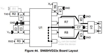
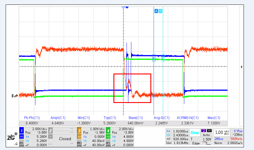
I check the datasheet, the layout recommend add a differential mode TVS tube. But when I let customer remove D900 and D907 as our datasheet, there are also oscillation as below picture. The blue and green waveform are D and R signals. The red waveform is differential output CAN_H-CAN_L.

Could you please help analysis this issue and give a guidance about how to add TVS tube? Thanks.

Best Regards.

Chen

  • Hi Chen,

    The TVS diodes are not required for the device to function, but can be useful in protecting the device if the transient immunity (ESD, etc.) requirements of the application exceed the rating of the IC itself.

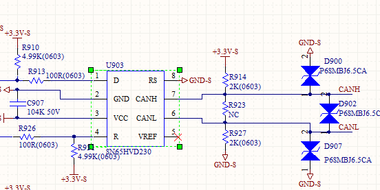
    There are a few things we could check to help reduce this ringing.  One is the parasitic capacitance of these diodes.  I couldn't find a datasheet for this part number to check it, but typically TVS diodes used for CAN buses would have capacitance in the 15-25 pF range.  If these are higher, it could degrade signal integrity.  In that case, you may want to try a different diode like PESD1CAN.

    Also, it is unusual for transient stresses to couple between the two lines - typically they would be between on or both lines and ground.  So, unless this application has a special requirement for this you could remove D902 but leave D900 and D907.

    There are some other things to consider outside just the TVS diodes as well.  How is termination implemented on the bus?  And, how are the nodes wired together - is it in a linear/daisy-chain fashion or is it more like a star where nodes connect to a main bus or central point via longer "stub" lines?

    Also, it isn't common to use pull-up/pull-down resistances on the CAN bus such as R914 and R927.  Can you please let me know the intention behind these resistances?

    Regards,
    Max

  • Hi, Max

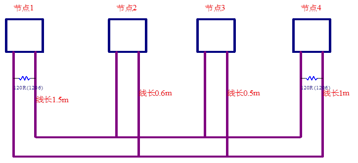
    Thanks for your kindly explanation, below is my customer's wiring with 120R load, could you please help check if there is any change need to do? Thanks. 


    In addition, the purpose of adding R914 and R927 pull up and pull down resistors is to add the buffer capability of BUS, is it necessary? 

    Best Regards.

    Chen


  • Chen,

    The wiring diagram looks OK to me.  The unterminated 0.5-m and 0.6-m lines will contribute to some ringing during the recessive period, but I expect it to be manageable.  I'd recommend testing without the pull-up/down resistances, though, since these are not needed.  They would cause a small positive differential bias during the recessive state which would result in less noise margin during this state.

    One other thing to note - I think if a hardware-based solution can be achieved by changing the resistances and TVS diodes it is best, but since the glitching happens early in the bit period you could also adjust the system to better tolerate it by shifting the sampling point configuration in the controller.

    Regards,
    Max