This thread has been locked.

If you have a related question, please click the "Ask a related question" button in the top right corner. The newly created question will be automatically linked to this question.

DS90UB936-Q1: Test Pattern Generation on DS90UB936-Q1 DeSerializer

Part Number: DS90UB936-Q1

Hi TI Team.

We are using DS90UB936-Q1 deserializer. We have 1 MIPI lane connected with our host processor. The resolution is 1280 x 720 at 30fps.

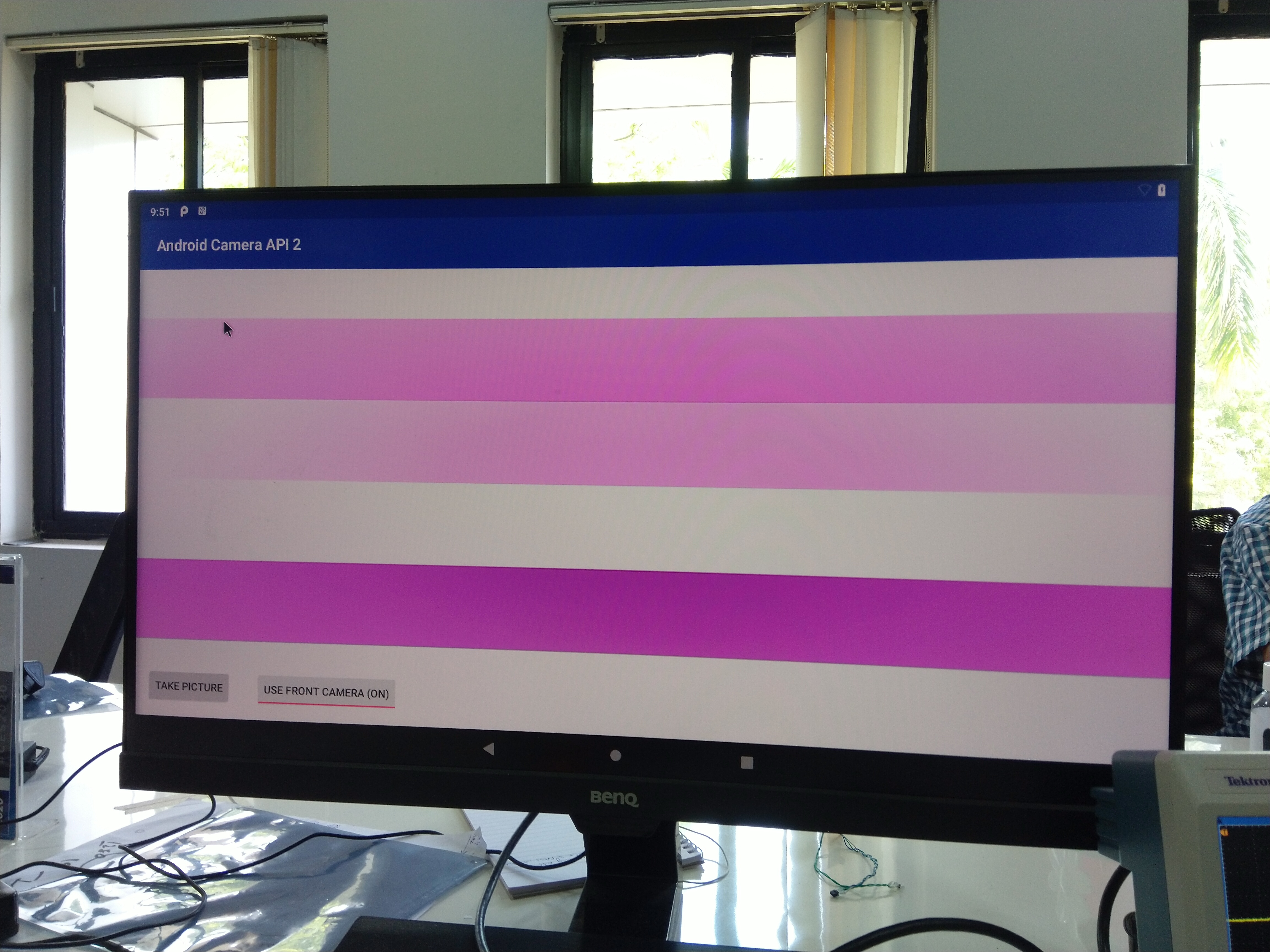
We want to generate test pattern on the deserializer. Below are the deserializer register settings done for this:

Reg:0x20 | Value: 0x30 # Forward Control Disabled for RX0 and RX1
Reg:0x1f | Value: 0x02 # CSI PLL : 1.6 Gbps
Reg:0x33 | Value: 0x33 # CSI enable, Continuous clocks, Lane Count=1
Reg:0xB0 | Value: 0x01 # Indirect Pattern Gen Registers - Select Pattern Block
Reg:0xB1 | Value: 0x01 # PGEN_CTL
Reg:0xB2 | Value: 0x01
Reg:0xB1 | Value: 0x02 # PGEN_CFG
Reg:0xB2 | Value: 0x33
Reg:0xB1 | Value: 0x03 # PGEN_CSI_DI
Reg:0xB2 | Value: 0x24
Reg:0xB1 | Value: 0x04 # PGEN_LINE_SIZE1
Reg:0xB2 | Value: 0x0F
Reg:0xB1 | Value: 0x05 # PGEN_LINE_SIZE0
Reg:0xB2 | Value: 0x00
Reg:0xB1 | Value: 0x06 # PGEN_BAR_SIZE1
Reg:0xB2 | Value: 0x01
Reg:0xB1 | Value: 0x07 # PGEN_BAR_SIZE0
Reg:0xB2 | Value: 0xE0
Reg:0xB1 | Value: 0x08 # PGEN_ACT_LPF1
Reg:0xB2 | Value: 0x02
Reg:0xB1 | Value: 0x09 # PGEN_ACT_LPF0
Reg:0xB2 | Value: 0xD0
Reg:0xB1 | Value: 0x0A # PGEN_TOT_LPF1
Reg:0xB2 | Value: 0x04
Reg:0xB1 | Value: 0x0B # PGEN_TOT_LPF0
Reg:0xB2 | Value: 0x1A

Despite of this, we are not getting any output on our host processor. (The MIPI lines on the host are working)

> Are the register settings correct ?
> What could be the probable reasons for not getting the output?

Regards,
Khilav

  • Hello Khilav,

    I don't see you setting the following parameters:

    Vertical Back Porch 

    Vertical Front Porch

    Vertical Sync 

    Line Period 

    If you send over your desired vertical timing parameters then we can back calculate the line period based on the vertical total and frame rate. 

    Best Regards,

    Casey 

  • Hi Casey,

    As per your comments below are the revised registers settings for pattern generation.

    Reg:0x20 | Value: 0x30 # Forward Control Disabled for RX0 and RX1
    Reg:0x1f | Value: 0x00 # CSI PLL : 1.6 Gbps
    Reg:0x33 | Value: 0x33 # CSI enable, Continuous clocks, Lane Count=1


    Reg:0xB0 | Value: 0x00 # Indirect Pattern Gen Registers - Select Pattern Block
    Reg:0xB1 | Value: 0x01 # PGEN_CTL
    Reg:0xB2 | Value: 0x01
    Reg:0xB1 | Value: 0x02 # PGEN_CFG
    Reg:0xB2 | Value: 0x33
    Reg:0xB1 | Value: 0x03 # PGEN_CSI_DI
    Reg:0xB2 | Value: 0x24
    Reg:0xB1 | Value: 0x04 # PGEN_LINE_SIZE1
    Reg:0xB2 | Value: 0x0F
    Reg:0xB1 | Value: 0x05 # PGEN_LINE_SIZE0
    Reg:0xB2 | Value: 0x00
    Reg:0xB1 | Value: 0x06 # PGEN_BAR_SIZE1
    Reg:0xB2 | Value: 0x01
    Reg:0xB1 | Value: 0x07 # PGEN_BAR_SIZE0
    Reg:0xB2 | Value: 0xE0
    Reg:0xB1 | Value: 0x08 # PGEN_ACT_LPF1
    Reg:0xB2 | Value: 0x02
    Reg:0xB1 | Value: 0x09 # PGEN_ACT_LPF0
    Reg:0xB2 | Value: 0xD0
    Reg:0xB1 | Value: 0x0A # PGEN_TOT_LPF1
    Reg:0xB2 | Value: 0x04
    Reg:0xB1 | Value: 0x0B # PGEN_TOT_LPF0
    Reg:0xB2 | Value: 0x1A

    REG: 0xB1 0x0C # PGEN_LINE_PD1
    REG: 0xB2 0x0C
    REG: 0xB1 0x0D # PGEN_LINE_PD0
    REG: 0xB2 0x67
    REG: 0xB1 0x0E # PGEN_VBP
    REG: 0xB2 0x21
    REG: 0xB1 0x0F # PGEN_VFP
    REG: 0xB2 0x0A

    >However, despite of setting these registers also, we are not getting any MIPI data for colour bars. 

    > Also this pattern is being generated for RGB888 format. I want the pattern generation for RAW10 data format for 1280x720 resolution at 30 fps for 1-Lane. Can you please share the register settings for this ?

    I am reiterating the fact that my MIPI lines on the SOC are working fine. We have already validated them.

    Regards,

    Khilav

  • Hello Khilav,

    Looking back at your first post, the issue looks like it is actually related to your CSI-2 PLL setting. Your code comments say 1.6Gbps/lane, but the 0x1F setting is 800Mbps/lane which is not enough to carry 1280x720@30 RGB888. You need to set 0x1F = 0x00 and also enable skew calibration 0x33 = 0x73

    However I see you adjusted the 0x1F setting in the second code but skew cal is not enabled which may be the issue. 

    For RAW10 can you make the following adjustments and try again?

    Reg:0x20 | Value: 0x30 # Forward Control Disabled for RX0 and RX1
    Reg:0x1f | Value: 0x00 # CSI PLL : 1.6 Gbps
    Reg:0x33 | Value: 0x73 # CSI enable, Continuous clocks, Lane Count=1, enable skew cal


    Reg:0xB0 | Value: 0x00 # Indirect Pattern Gen Registers - Select Pattern Block
    Reg:0xB1 | Value: 0x01 # PGEN_CTL
    Reg:0xB2 | Value: 0x01
    Reg:0xB1 | Value: 0x02 # PGEN_CFG
    Reg:0xB2 | Value: 0x33
    Reg:0xB1 | Value: 0x03 # PGEN_CSI_DI
    Reg:0xB2 | Value: 0x2B
    Reg:0xB1 | Value: 0x04 # PGEN_LINE_SIZE1
    Reg:0xB2 | Value: 0x06
    Reg:0xB1 | Value: 0x05 # PGEN_LINE_SIZE0
    Reg:0xB2 | Value: 0x40
    Reg:0xB1 | Value: 0x06 # PGEN_BAR_SIZE1
    Reg:0xB2 | Value: 0x00
    Reg:0xB1 | Value: 0x07 # PGEN_BAR_SIZE0
    Reg:0xB2 | Value: 0xC8
    Reg:0xB1 | Value: 0x08 # PGEN_ACT_LPF1
    Reg:0xB2 | Value: 0x02
    Reg:0xB1 | Value: 0x09 # PGEN_ACT_LPF0
    Reg:0xB2 | Value: 0xD0
    Reg:0xB1 | Value: 0x0A # PGEN_TOT_LPF1
    Reg:0xB2 | Value: 0x04
    Reg:0xB1 | Value: 0x0B # PGEN_TOT_LPF0
    Reg:0xB2 | Value: 0x1A

    REG: 0xB1 0x0C # PGEN_LINE_PD1
    REG: 0xB2 0x0C
    REG: 0xB1 0x0D # PGEN_LINE_PD0
    REG: 0xB2 0x67
    REG: 0xB1 0x0E # PGEN_VBP
    REG: 0xB2 0x21
    REG: 0xB1 0x0F # PGEN_VFP
    REG: 0xB2 0x0A

    Best Regards,

    Casey 

  • Hi Casey,

    I tried with the register settings you provided, but I am still not getting data.

    Further, I also changed register 0x02 (of indirect mapping) to 0x35 in order to change block size for RAW10 mode to 5. I kept all the other registers similar as given for RAW10 mode. Despite of this, I am not getting any pattern data.

    Could you please help me with this ?

    Regards,

    Khilav

  • Hi Khilav,

    The register configuration seems fine. Are you able to send us your schematic so we can see if the issue is with that?

    Regards,

    Carrie

  • Hi Carrie,

    We were able to achieve the test pattern but all the colours look pinkish (Test pattern generated for 8 colour bars with RAW10 data format at a res of 1280x720).

    Below is the picture of the same.

    Below are all the register settings we have done:

    Reg:0x20 | Value: 0x30 # Forward Control Disabled for RX0 and RX1
    Reg:0x1f | Value: 0x03 # CSI PLL : 400 Mbps (with 1.6 Gbps we  
    Reg:0x33 | Value: 0x73 # CSI enable, Continuous clocks, Lane Count=1, enable skew calib
    Reg:0xB0 | Value: 0x00 # Indirect Pattern Gen Registers - Select Pattern Block
    Reg:0xB1 | Value: 0x01 # PGEN_CTL
    Reg:0xB2 | Value: 0x01
    Reg:0xB1 | Value: 0x02 # PGEN_CFG
    Reg:0xB2 | Value: 0x33
    Reg:0xB1 | Value: 0x03 # PGEN_CSI_DI (for RAW10)
    Reg:0xB2 | Value: 0x2B
    Reg:0xB1 | Value: 0x04 # PGEN_LINE_SIZE1
    Reg:0xB2 | Value: 0x06
    Reg:0xB1 | Value: 0x05 # PGEN_LINE_SIZE0
    Reg:0xB2 | Value: 0x40
    Reg:0xB1 | Value: 0x06 # PGEN_BAR_SIZE1
    Reg:0xB2 | Value: 0x00
    Reg:0xB1 | Value: 0x07 # PGEN_BAR_SIZE0
    Reg:0xB2 | Value: 0xC8
    Reg:0xB1 | Value: 0x08 # PGEN_ACT_LPF1
    Reg:0xB2 | Value: 0x02
    Reg:0xB1 | Value: 0x09 # PGEN_ACT_LPF0
    Reg:0xB2 | Value: 0xD0
    Reg:0xB1 | Value: 0x0A # PGEN_TOT_LPF1
    Reg:0xB2 | Value: 0x04
    Reg:0xB1 | Value: 0x0B # PGEN_TOT_LPF0
    Reg:0xB2 | Value: 0x1A
    REG: 0xB1 0x0C # PGEN_LINE_PD1
    REG: 0xB2 0x0C
    REG: 0xB1 0x0D # PGEN_LINE_PD0
    REG: 0xB2 0x67
    REG: 0xB1 0x0E # PGEN_VBP
    REG: 0xB2 0x21
    REG: 0xB1 0x0F # PGEN_VFP
    REG: 0xB2 0x0A

    Could you please tell us why this is happening? How do we get solid colour bars that are not pinkish?

    Regards,

    Khilav Soni

  • Hello Khilav,

    Can you send a register dump for your pattern generator color registers as well? (Indirect access page 0x00 registers 0x10 to 0x1E) These determine the color of the pattern. The pink bars are likely due to the display's interpretation of the RAW10 format. 

    Can you also send a full register dump for all of the direct access registers?

    Finally, is this image cropped or rotated in any way? If so, please send the raw image as well.

    Thanks,

    Carrie

  • Hi Carrie


    We are able to grab data with this combination. There is no pinkish issue with the grabbed data.

    But the image is rotated 90 degrees clockwise. Why is this so ? Are there any settings in the deserializer to rotate the image ?

    Regards,

    Khilav

  • Hello Khilav,

    Our chip cannot display horizontal bars. The only pattern it can output is horizontal. If you are seeing vertical bars, this may be a problem with the settings of your SOC.

    Regards,

    Carrie

  • Hi Carrie,

    You reply sounds very ambiguous. 936A-Q1 DeSer display vertical or horizontal bars ??

    Please reply again.

    Regards,

    Khilav

  • Khilav,

    The pattern generator output is always vertical bars. It can not output horizontal bars 

    Best Regards,

    Casey 

  • Hello Khilav,

    Sorry for the confusion, Our chip can only display vertical bars. It cannot display horizontal bars.

    Regards,

    Carrie