This thread has been locked.

If you have a related question, please click the "Ask a related question" button in the top right corner. The newly created question will be automatically linked to this question.

THVD1552: CAN /RS-485

Part Number: THVD1552

Hello TI Community,

Has anyone experienced with using an RS-485 transceiver to communicate with a CAN bit stream from a u-controller?

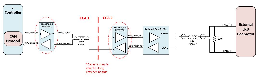
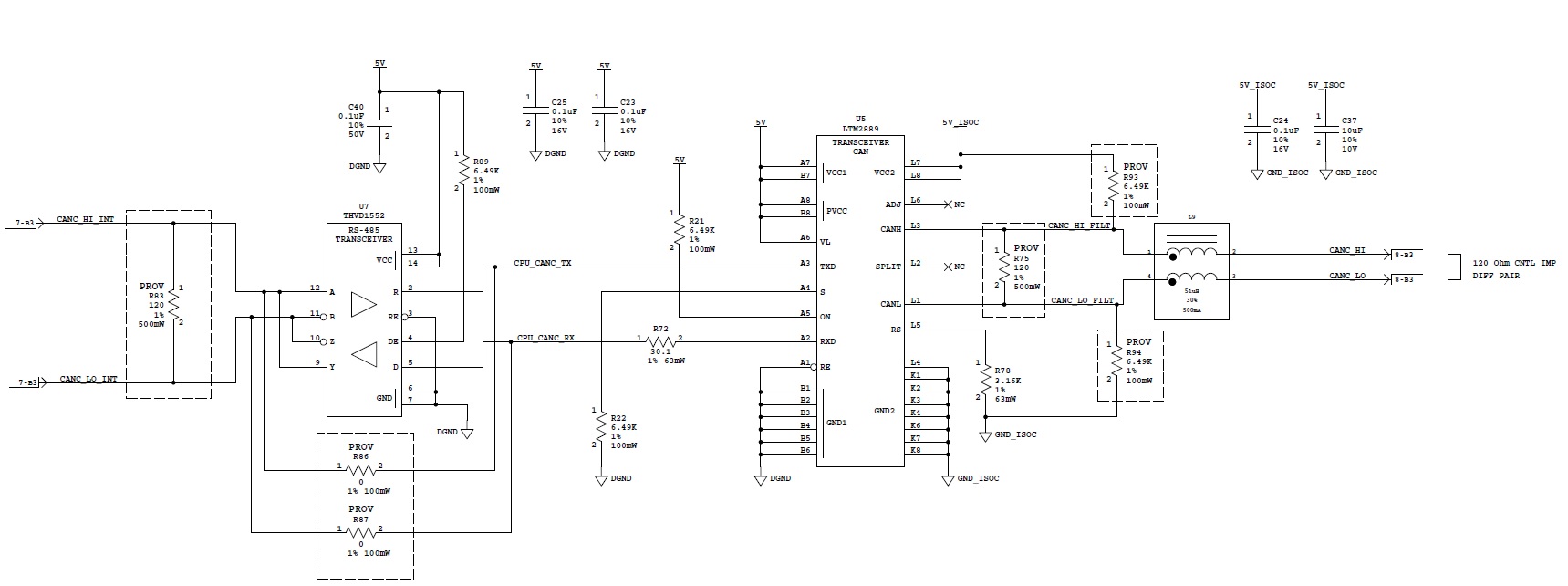
I'm communicating from one board to another in a potentially noisy environment so going from the u-controller CAN Tx/Rx pins, to an RS-485 (full duplex), to an RS-485 on the other board, to the CAN transceiver, then out of the box to interface to another CAN transceiver down stream. It seems like this could work, but would like some feedback.

Thank you for your support with this.

  • Hi Brian,

    There would be some challenges in using the RS-485 physical layer for the CAN protocol here.  For one, the CAN controller typically expects to see the RXD line matching whatever is sent on TXD (or else it considers the condition a transmit error).  That could be solved by using a half-duplex transceiver rather than a full-duplex one (CAN is always half-duplex in nature), but you would still have an issue of being able to support cases where multiple nodes might need to be active simultaneously (such as the arbitration phase or the ACK delimited of a CAN message).  The CAN physical layer allows for this by defining the transceivers to only strongly drive the signal in one polarity. (So, if any node is "dominant" the bus is dominant; the bus is "recessive" if all nodes are recessive.)  RS-485 drives both positive and negative polarities, though, so if you had two transceivers driving opposite states it would be a problem (high current would flow and an indeterminate voltage level would result.

    If you did want to set up CAN communication using RS-485 transceivers, you could accomplish similar dominant/recessive signaling by sending data on the "DE" control line rather than the "D" input.  This is how the J1708 physical layer works.  You would need to invert TXD and connect it to DE, tie D and /RE to GND, R to RXD, pull the A pin high through a resistance, and pull the B pin low through a resistance.  That way, TXD = 1 corresponds to a "recessive" state where the RS-485 driver is high-Z and a positive (logic-high) differential signal is set on the bus externally via the pull-up/pull-down resistances, and TXD = 0 corresponds to a "dominant" state where the RS-485 driver produces a negative (logic-low) differential output.

    Note that this physical layer solution may not directly interoperate with CAN transceivers (since those would use different output signal levels and input thresholds.  But if all nodes were designed using this methodology the network could be used for communication using the CAN protocol.

    Please let me know if this isn't clear or if you have further questions.

    Regards,
    Max

  • Thank you for the detailed response Max!

    Given the additional design constraints and also the impact it may have to the propagation delay, I would prefer to use a different approach.

    Would I be able to use another CAN transceiver in place of the RS-485 component? (we need to be isolated so that's the reason why I can't place the CAN transceiver on CCA 1). 

    Is there a simple buffer that I may be able to use to drive the single ended Tx/Rx signals across the 20in cable harness?

    Having a differential signal across the cable harness is my goal in order to avoid the impact due to the noisy environment. but maybe there's a buffer that works well.

    Thanks again for your help.

  • Hi Brian,

    Did you try to post an image?  If so, will you please try to re-post?  I see a broken image icon in your post.  I think that may help me better understand what you are trying to do.  Otherwise, I'm not understanding in what situation you would be able to place an RS-485 transceiver but not a CAN transceiver (which would of course be the straightforward answer to this problem).

    It's possible to use open-drain logic buffers (or simply blocking diodes) and pull-up resistances to be able to interconnect TXD/RXD lines from multiple MCUs without using a transceiver.  You can find some discussion on the topic here: https://e2e.ti.com/support/microcontrollers/c2000/f/171/t/605836.  However, this technique is typically not suitable for noisy environments or if there is any potential for ground offsets between MCUs.  For that differential signaling is needed.  (The high-Z "recessive" state would be particularly susceptible to noise coupling, and differential signaling ensures that this noise manifests predominately as "common mode" noise which is rejected by a CAN receiver.)

    Regards,
    Max

  • Thanks Max,

    Here's the image, hopefully it provide more details in what I'm attempting to accomplish. Somewhere on CCA 2, I would need an isolated CAN transceiver to meet EMI requirements, so the design is getting more complicated. The cable harness I'm describing between CCA 1 and CCA 2 is inside our box.

  • Brian,

    Thanks for the image.  I misunderstood what you were going after.  Now that I see this and re-read your initial post (and had some coffee) I get it.  If the "bus" connection to other nodes remains via a CAN transceiver and you are just using RS-485 to extend the controller-to-transceiver interface then things are much more straightforward.  You could use the THVD1552 in this way without any kind of special logic.  The main limiting factor to consider with this would be the additional propagation delay, since for the CAN protocol to work well you would want to make sure the round-trip delay (i.e., from MCU through the RS-485 TX-direction link to the CAN transceiver to the cable to the furthest node and back through the cable and RX-direction RS-485 link) is less than one arbitration bit period.  

    Just in terms of functionality, a push-pull logic buffer could replace the RS-485 transmitter if you wanted to keep the signals single-ended.  I think whether or not that would be a good idea would come down to more system-specific concerns such as the required EMI performance (which would be worse in terms of emissions and immunity compared to a balanced differential solution) and the severity of any power/ground offsets between CCA 1 and CCA 2 (which could restrict the ability to receiving side to correctly determine high/low logic states).  

    Regards,
    Max

  • Thanks Max,

    Really glad that this could work, you had me sweating there for a minute. I'll collect the information for the propagation delay.

    I would like to share the schematic with my concern being the bus connections (shorting A/Y and B/Z).

    Is this possible since CAN is really half-duplex or should I separate those two pairs?

    Also on the CCA 2 (2nd image), it's interesting to see that the 485 receiver output 'R' will connect to the CAN transceiver 'TxD', is this correct?

  • Brian,

    You can always tie A/B to Z/Y to convert a full-duplex transceiver into a half-duplex one, but the challenge here comes in controlling the "enable" lines.  In a half-duplex set-up you need to be careful to only have one driver enabled at any given time.  So, tying "DE" high on one side like you've done here would not be an option.  I think using a four-wire full-duplex setup (one diff pair for TX, one diff pair for RX) would make more sense here given that the CAN controller needs to be able to control the TXD input of the CAN transceiver while simultaneously reading its RXD state.

    Besides that, though, the TX/RX designations make sense.  The names are just a little confusing because of the different transceivers used.  On CCA2, the signal that is received by the 485 receiver (R) is what needs to be transmitted by the CAN transmitter (TXD) and the signal that is received by the CAN receiver (RXD) is what needs to be sent back to the controller by the 485 transmitter (D).

    Regards,
    Max

  • Thanks for all your help Max!

    I understand what I need to do now in leaving the DE pin connected high on CCA 2 and using two different pairs for Tx and Rx?

    I'll also be sure to capture the propagation delay to make sure it's acceptable. 

  • That's right.  If you use independent differential pairs for the MCU-to-CAN-transceiver TXD signal and the CAN-transceiver-to-MCU RXD signal then you can keep each pair enabled all the time (DE pulled high, /RE pulled low) and they will pass through the data just like if it were a direct MCU/transceiver connection (just with some added delay due to the differential conversion and propagation over cable).

    Max