This thread has been locked.

If you have a related question, please click the "Ask a related question" button in the top right corner. The newly created question will be automatically linked to this question.

TUSB9261: Connects at SuperSpeed when connected to a USB3.0 port and at High-Speed when connected to a USB3.1 port.

Part Number: TUSB9261
Other Parts Discussed in Thread: 3220UFP-DGLEVM, , HD3SS3220

Dear TI Support,

I am testing a prototype board based upon the combination of the TUSB9261 DEMO and 3220UFP-DGLEVM evaluation boards. 

When the board is plugged into a Type-C port capable of up to USB3.0 the board connects to the PC as a SuperSpeed device.  When the board is plugged into a PC with a Type-C port capable of running at USB3.1 the board connects as a a High-Speed device. I have tested an actual 3220UFP-DGLEVM plugged into a TUSB9261 DEMO and this setup always connects at SuperSpeed regardless of the PC it is connected to. 

I have looked at the debug logs on my design in both cases. When plugged into a USB3.0 port the TUSB9261 transitions from RX detect to POLLING. When connected to a USB3.1 port the TUSB9261 never goes into polling state and instead transitions into USB2.0 mode and enables the pull up on the USB2.0 line. This leads me to believe that the RX detect state is failing. 

I have two main questions:

- Is there a way to get more debug information out of the TUSB9261 other than the information which is sent out by default?

- Do you have any ideas about what might be causing the TUSB9261 to connect at High-Speed on some PCs and SuperSpeed on others?

Thank you in advance for your help.

Kind Regards,

Peter Bouvy


  • Hi Peter,

    Unfortunately the debug messages output TUSB9261 are the only debug messages provided by TUSB9261. You may be experiencing a problem listed in the TUSB9261 Errata depending on your testing methods. Please review the first problem and workaround listed in the document linked below and let me know if this sounds like your problem. 

    https://www.ti.com/lit/er/sllz065b/sllz065b.pdf

  • Hi Malik,

    Thanks for your suggestion. Unfortunately this is not the issue I am experiencing. The TUSB9261 is not plugged into a hub. It is plugged into a port on the PC directly and is bus powered. 

    So there is no way that VBUS can stay high when the USB is disconnected. 

    Thanks,

    Peter

  • Hi Peter,

    Could I review a schematic for your prototype board? 

  • Hi Malik,

    I have attached a partial schematic for my board. The parts missing are all downstream of the SATA port. Which has been working correctly. The problem appears to be an issue with the speed of the USB interface only. 

    Some additional background on the schematics which may help. 

    • The TUSB9261 Reset signal is held at ground for 25ms after power up up and then released to 3.3V with a rise time of 15ns.
    • The 3.3V and 1.1V rails come up at approximately the same time.  (Within 100us of each other)
    • U13 is acting like the jumper on the TUSB9261 DEMO to allow for reprogramming of the firmware

    It appears that when the TUSB9261 connects at high-speed the TUSB9261 fails to detect termination of the super speed data lines at the PC. It appears that the PC is successfully seeing termination of the RX lines on the TUSB9261. 

    I cannot provide any details for what is connected to the SATA port of bridge, but as the SATA link has been functioning correctly I think it is safe to assume that this is not the cause of the issue.

    Thanks,

    PeterPeterBouvy_TUSB9261_Schematic.pdf

  • Hi Peter, 

    Sorry for the delay here. I am still looking into this and hope to get back to you tomorrow. 

  • Hi Peter,

    In reviewing the schematic I noticed one thing

    • TX1/2 should be AC coupled with 220nF and RX1/2 should be AC coupled with 330 nF. This is highly recommended when AC coupling a high speed mux to USB connector. This is an updated recommendation from the 3220UFP-DGLEVM.

    I would like to confirm if HD3SS3220 is actually configured correctly when plugged into a USB 3.1 port. What is the state of DIR in the scenrio and does it match with the orientation of the coonection? Can you probe on Tx1 (or TX2) to see the RX detect pulse from TUSB9261? (you may have already done this). If you are able to capture any USB traces between your device and PC it would to help as well. Have you tried multiple PCs with USB 3.1?

  • Hi Malik,

    Thank you I will try changing the AC coupling capacitors to the values you suggested.

    I should clarify that both ports are Type-C just that in one case the port is USB3.0 capable and the other is USB3.1 capable. So in both cases the signals are passing through the Multiplexer.

    I have tried multiple PCs with USB3.1 type-c ports and none work. I do not have a USB protocol analyser but have probed the TX1/TX2 and RX lines and measured the RX Detect waveforms. (Please See Attached zip file). I have also probed the same signals on my evaluation board setup for comparison. In all plots yellow is the 3.3V supply, and pink is the TX or RX positive signal. Reset for the TUSB9261 is released 25ms after the 3.3V rails comes up. 

    TX1/TX2

    Plugged into the USB3.0 port I see the RX detect pulses then what looks like the polling signals. Attached to USB3.1 I see the RX detect signals on TX1 multiple times before the maximum number of attempts is reached and the TUSB9261 enables the USB2.0 pull-up. Measuring the evaluation setup I see the RX detect pass and polling occur afterwards. The shape of the RX Detect (see the captures labeled RX_Detect_Detail) is different between the eval board setup and the prototype. Which explains why this step fails. 

    RX 

    It appears that even attached to a USB3.1 port the PC can detect the termination of the RX lines at the TUSB9261 as it stops sending RX detect pulses long before the USB2.0 pull-up is enabled. And the shape of the RX detect observed (see Detail captures) is the same evaluation setup to prototype. It appears this side of the link is operating as expected. 

    I am fairly certain that the multiplexer is switching correctly, as it is working when attached to the USB3.0 type-c ports. And flipping the cable results in a swap in TX1 or TX2 getting the RX-Detect signals. The issue appears to be with the termination observed by the TUSB9261 TX pairs. Perhaps your suggestion of moving from 470nF capacitors to 220nF and 330nF capacitors may help with this.

    I am currently investigating the timing of power rails. As I have observed small differences between my prototype and the evaluation boards here. 

    Thanks for your help,

    Peter

    Traces to Send to TI.zip

  • Hi Peter,

    I agree that changing the AC coupling should help here. It seems that the equivalent capacitance on the bus is causing a shift in common mode voltage and distortions in the RX detect from TUSB9261. 

  • Hi Malik,

    Unfortunately changing the Coupling capacitors does not seem to have made a difference. It appears that when the TUSB9261 is in RX.Detect the receiver pins of the PC are unterminated. I ran a test where 5V was supplied to the prototype from an external supply and I monitored the RX.Detect signals sent from the TUSB9261. The signals seen on the TX pins in this test are identical to those observed when connected to PCs that connect at USB2.0. 

    What is unclear is why this is the case. Something must be occurring which is causing the PC to disconnect its reliever termination. My understanding is that in all LTSSM states but SS.Disabled a USB3.0 port will have its receiver terminated. Do you know what could be causing the PC to enter this state? I have ruled out the USB2.0 pull up as a cause. Could poor performance during the polling state cause the PC to enter SS.Disabled?

    Cheers,

    Peter

  • Hi Malik,
     
    I have been investigating the relative timing of the RX detect signals on the TX and RX lines of the TUSB9261. When connected to PCs that connect at USB2.0 the following signal behaviour is observed.
     
    The host PC starts its RX.Detect first. The RX detect signal pulses sent by the PC occur at consistent intervals before stopping. The pulses stop at approximately one of these intervals before the TUSB9261 sends its first RX.Detect attempt. As I see no evidence of the PC attempting polling my current hypothesis is that the RX detect of the PC is not stopping due to detecting correct termination but for some other reason. 
     
    By the time the TUSB9261 sends its first RX detect attempt the PC has its receiver unterminated. Suggesting that something has occurred that has caused the PC to enter the LTSSM SS.Disabled state. Probably the same event which caused the PC to stop RX.Detect.
     
    My setup with evaluation boards connects at USB3.0 when connected to the same PC and I observe the signal behaviour below. 
     
    The host PC also starts its RX.Detect first at the same consistent intervals as before. This time however these pulses continue to be sent until after the TUSB9261 has sent out it's RX.Detect. The TUSB9261s RX.Detect appears to pass the first try. The RX detect from the PC then appears to pass a couple of attempts after the TUSB9261 RX.Detect passes. After both of the RX.Detect signals pass I can see the polling signals being sent in both directions. 
     
    So in summary the problem appears to be that before the TUSB9261 attempts its RX.Detect an event is occurring that causes the host PC port to enter SS.Disabled. Do you know of any particular failure modes which would show such behaviour?
     
    image.png
    Prototype.png
  • Hi Peter,

    Sorry for the delay here. Not sure if TUSB9261 is the issue here. As you point out the PC seems to stop RX.Detect even before TUSB9261 has sent its first RX.Detct pulse, this is strange. This does not seem to correlate with any particular timeout in the LTSSM. Whats interesting is that this only occurs with your prototype board and not the EVMs. 

    From an LTSSM perspective the only way to enter SS.Disable from RX.Detect is to enter the Polling state and trip the tPollingIdleTimeout which is 2 ms (shortest possible path). What is the timing you are seeing in your test setup? Also could you use a multi-meter to directly measure the single-ended termination presented at the PC and prototype board. This will help us tell what termination are actually on or off. 

  • Hi Malik,

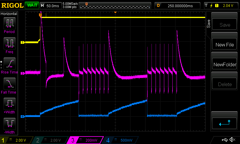
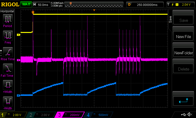
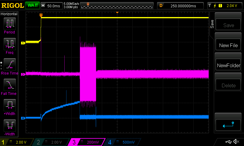
    I have done a test to assess the termination of the PCs RX pins over time. In this test I have injected a 50mV 1MHz sine wave into the TX lines at the Type-C connector. This signal is fed into both the positive and negative wires through 5K resistors.  In the plots below the pink waveform shows the signal on the TX line. The yellow trace is the boards 3.3V supply. This supply comes us approximately 5ms after VBUS is a stable 5V. You can ignore the blue trace.

    When the receiver of the PC is terminated I would expect the sinusoid to not be visible as the resistance between by signal generator and the TX lines is much higher than the receivers resistance to ground when terminated. 

    Connected to the PC that works the sinusoid I injected is never visible. This suggests that the PC has its RX lines terminated at all times (this matches the USB3.0 Spec). Connected to the PCs which are not working the sinusoid is visible to varying degrees over time. Before the TUSB9261 and multiplexer are powered the sinusoid is fully visible (suggesting the RX of the PC is unterminated even before my board powers on!). Then throughout the TUSB9261s various attempts at RX detect the amount the sinusoid is visible varies. This second part is harder to interpret. 

    Any light you can shed on this behavior would be very helpful.  

    PC Not Working (No Sine Wave Injected)


    PC Not Working (Sine Wave Injected)


    PC Working (With or Without Sine Wave Injected)


    Thanks,

    Peter

  • Hi Peter,

    I am looking into this and will get back into you early next week if I am able to shed any light on the PCs behavior. 

  • Hi Peter,

    After reviewing everything again I would like you try removing the AC coupling caps (and pull down resistors) in between TUSB9261 and HD3SS3220. This will allow TUSB9261 to DC bias HD3SS3220. I believe that the AC coupling is the issue here. I am assuming that you have changed the AC coupling in between HD3SS3220 and the connector to the following recommendation: TX1/2 should be AC coupled with 220nF and RX1/2 should be AC coupled with 330 nF.

  • Hi Malik,

    Do you mean that the RX 1 and RX2 pairs should have series capacitiance on the connector side of the multiplexer? Or that the series capacitance on the RX lines on the TUSB9261 side of the multiplexer (originally 470nF) should be changed to 330nF.  

    Putting series capacitance on the RX lines on the connector side will be difficult as there are no footprints on the board for them.

    I will try removing the series capacitance on the TX pair on the TUSB9261 side of the multiplexer and see if this makes a difference. 

    Thanks,

    Peter

  • Hi Peter,

    Yes I was referring to the AC coupling on RX1 and RX2 (connector side of the mux).