This thread has been locked.

If you have a related question, please click the "Ask a related question" button in the top right corner. The newly created question will be automatically linked to this question.

DS92LX1622: how to establish a simple link between DS92LX1621 & DS92LX1622

Part Number: DS92LX1622
Other Parts Discussed in Thread: DS92LX1621

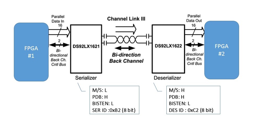
I am trying to establish a very simple communication link  between DS92LX1621 & DS92LX1622.
I have no plan to have any I2C remote device (e.g. camera) and not intrested in "I2C Pass Through" feature.
i just need to send some parallel data (16 bit) through the diferantial link of DS92LX1621 & DS92LX1622.
here is a scheme :


which registers shall be programed for this comunication?
here is what i have implementer so far:
=============
SER ID = 0xB2 (8 bit addr)
DES ID = 0xC2 (8 bit addr)
=============
1)Perform Remote Wake Up Sequence ==> Datasheet page 34 ,REMOTE WAKE UP section
Write 0xC0 to register 0x26 of  DS92LX1622
Write 0x04 to register 0x01 of  DS92LX1622
Write 0x00 to register 0x26 of  DS92LX1622

2)Set DES to normal operation mode ==>Datasheet page 24, Table2
Write 0xE0 to register 0x27 of  DS92LX1622

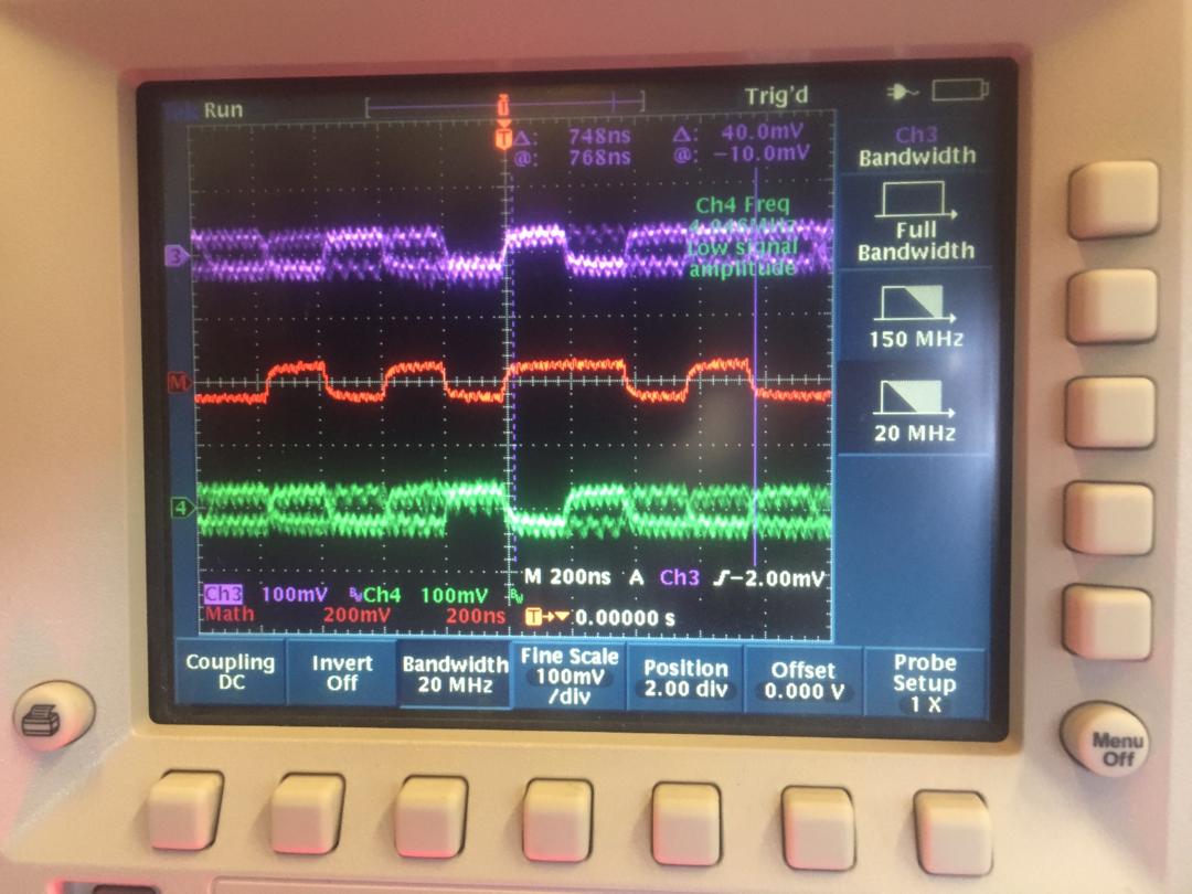
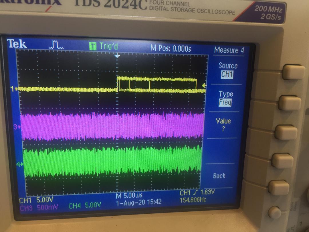
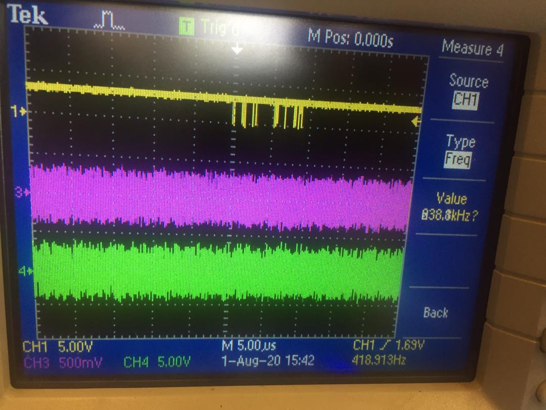
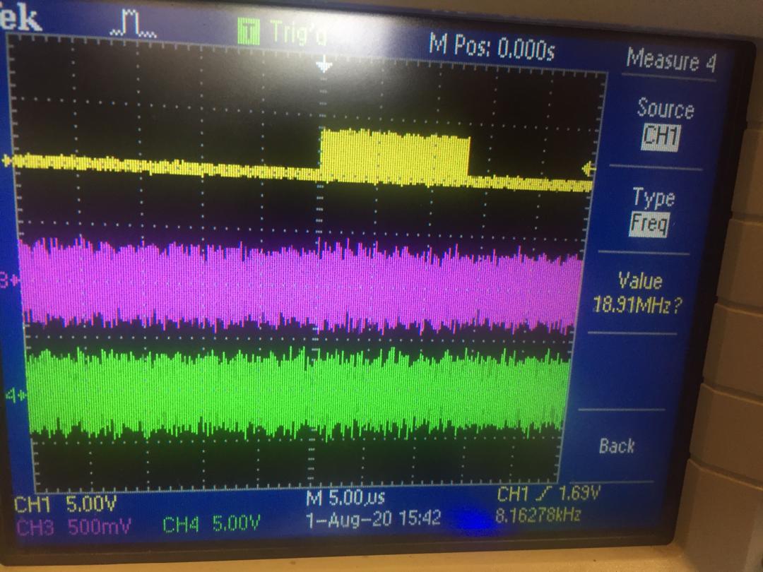
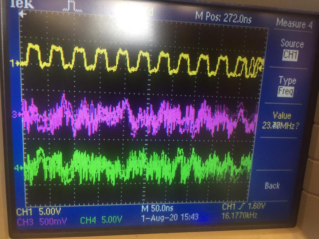
here is the link scope shot:


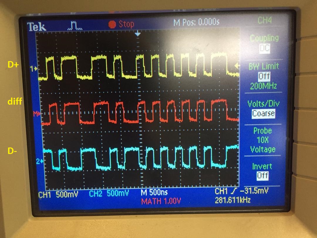
DS92LX1622 is not locked (LOCK=LOW and PASS=High)
and there is no PCLK or ROUT available on DSS92LX1622.
what is missing?


  • Hi,

    In your setting, it sounds you need wake up ser part 1611 from 1622, please make sure you follow up the design request in d/s as you mentioned, but from the captured plot above, we only can find the back channel signal and the link has no forward signal from 1611 to 1622 (~Gbps level). so we can deduce this chip 1611 still in sleep mode or power down mode.

    so please double confirm M/S & PDB key signals in your design, also pls check if the PCLK signal to 1611 is alive or not?

    REMOTE WAKE UP (Camera Mode) After initial power up, the SER is in a low-power Standby mode. The DES (controlled by host controller) 'Remote Wake-up' register allows the DES side to generate a signal across the link to remotely wake-up the SER. Once the SER detects the wake-up signal, the SER switches from Standby mode to active mode. In active mode, the SER locks onto PCLK input (if present), otherwise the on-chip oscillator is used as the input clock source. Note the host controller should monitor the DES LOCK pin and confirm LOCK = H before performing any I 2C communication across the link. For Remote Wake-up to function properly: • The chipset needs to be configured in Camera mode: SER M/S = 0 and DES M/S = 1 • The SER expects remote wake-up by default at power on. • Configure the control channel driver of the DES to be in remote wake up mode by setting DES register 0x26 to 0xC0. • Perform remote wake up on SER by setting DES register 0x01 b[2] to 1. • Return the control channel driver of the DES to the normal operation mode by setting DES register 0x26 to 0. The SER can also be put into standby mode by programming the DES remote wake up control register 0x01 b[2] REM_WAKEUP to 0.

    regards,

    Steven

  • Junqiang Shi said:
    from the captured plot above, we only can find the back channel signal and the link has no forward signal from 1611 to 1622 (~Gbps level). so we can deduce this chip 1611 still in sleep mode or power down mode.

    1- could you please clarify more on the backchannel signal and how it transfers along with the channel link III? shall there be only one ~GHz signal ?

    2- unfortunately, I do not have GHz bandwidths scope I am using TDS3054C may it be because of the limited bandwidth of my scope?

    here other screenshots:

    FULL BANDWIDTH

    20MHZ BANDWIDTH

    Junqiang Shi said:
    pls check if the PCLK signal to 1611 is alive or not

    I am not driving the PCLK of 1611.it is unconnected, I also connected a 20 MHZ signal to it T but nothing changed.

    Junqiang Shi said:
    REMOTE WAKE UP (Camera Mode) After initial power up, the SER is in a low-power Standby mode. The DES (controlled by host controller) 'Remote Wake-up' register allows the DES side to generate a signal across the link to remotely wake-up the SER. Once the SER detects the wake-up signal, the SER switches from Standby mode to active mode. In active mode, the SER locks onto PCLK input (if present), otherwise the on-chip oscillator is used as the input clock source. Note the host controller should monitor the DES LOCK pin and confirm LOCK = H before performing any I 2C communication across the link. For Remote Wake-up to function properly: • The chipset needs to be configured in Camera mode: SER M/S = 0 and DES M/S = 1 • The SER expects remote wake-up by default at power on. • Configure the control channel driver of the DES to be in remote wake up mode by setting DES register 0x26 to 0xC0. • Perform remote wake up on SER by setting DES register 0x01 b[2] to 1. • Return the control channel driver of the DES to the normal operation mode by setting DES register 0x26 to 0. The SER can also be put into standby mode by programming the DES remote wake up control register 0x01 b[2] REM_WAKEUP to 0.

    yes as i mentioned in my first post i am folowing the same ( Datasheet page 34,REMOTE WAKE UP section)

  • Hi, 

    both back channel signal and forward channel signal are transmitted in the same high speed diff. interface, in your last picture labled as FULL BANDWIDTH, it really includes both forward channel high speed signal (~Gbps) and back channel low speed signal (~5Mbps), this is different from the first picture attached by you. 

    regards,

    Steven

  • hi , thanks for the answer

    Junqiang Shi said:
    last picture labled as FULL BANDWIDTH, it really includes both forward channel high speed signal (~Gbps) and back channel low speed signal (~5Mbps)

    so it means that 1611 is waked up correctly by 1621. so 1622 shall " LOCK " but it doesn't. 

    is there any other configurations rather than i mentioned in my first post ?

    there is no PCLK or ROUT available on DSS92LX1622.
    what is missing?

  • Hi,

    I'm curious of your test result, why in the two times test the results are different.

    also, it is better if you can check the FC rate with ~2GHz bandwidth scope, the 1622 should be locked to this high speed serial signal if it is right.

    regards

    Steven

  • Junqiang Shi said:

    I'm curious of your test result, why in the two times test the results are different.

    the first pic was taken using 200Mhz scope, the second was with 500Mhz one.

    just to make sure, when 1621 is sending sth like above it means that it is working? right? is there any need to config a special register in it? (e.g slave I2C addr ,DES I2C addr ,....)

    btw: i do not want to use I2c I2C Pass-Through.

  • Hello,

    please check:

    1. scope with either the 200M or 500M bandwidth should not have so big difference when you measure the high speed serial signal. so for the last one, i think the link should run up, please check if the LOCK is ok or not?

    2. in your link,once the 1611 is waken up, if 1622 is not unlocked, please check the power supply of 1622.

    3. no other registers are required to run up the link. also the back channel must be used to wake up the ser. in your application.

    Rgds,

    Steven

  • Junqiang Shi said:

    2. in your link,once the 1611 is waken up, if 1622 is not unlocked, please check the power supply of 1622.

    I checked power supply of 1622, one mistake was there and VDDCML pin was not connected to VDD

    here is what I get after fixing that:

    why lock pin is High for only some microseconds?

    LOCK pin:

    PASS Pin:

    1622 PCLK pin :

    1622 PCLK pin : (zoomed)

  • Hi

    what is the ch3/ch4 in the plot?

    It sounds your link has transmission error so lock pin indicates the link unlock. you can check cable etc. in your case.

    anyway it seems your link is running up.

    regards

    Steven

  • Junqiang Shi said:
    what is the ch3/ch4 in the plot?

    it is the channel link (Dout+-/Rin+-)

    I was using 1621 with internal CLOCK source, I changed it to external PCLK=40Mhz  and Now LOCK and PASS  pins are High, and it seems to work.

    I drive DIN(0-15)  pins with 10Mhz signals and could see the same on ROUT(0-15). why the internal CLK  for 1621 did not works

  • Hi, Yes. If you use the internal clock, no data is outputted in the paralell output pin.

    regards,

    Steven