This thread has been locked.

If you have a related question, please click the "Ask a related question" button in the top right corner. The newly created question will be automatically linked to this question.

DS110DF111: parameter adjustment

Part Number: DS110DF111

Hi Sir,

Our application is support 1.25 Gbps (1G SFP) and 10.3125 Gbps (10G SFP+).

some question about the register setting.

1. From datasheet page 21 (table 9), i know the default datarates are Group 0 = 1.25 Gbps and Group 1 = 10.3125 Gbps. (i guess the 00 means 10.3125 Gbps, but how about 01,10 and 11? )

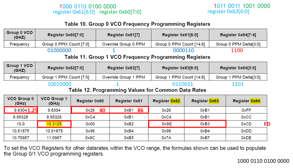
2. and also i follow page 22 (table 13 and 14), to Calculate Group 0 and Group 1 Register 0X60-0X64. But the function still can't work.(the setting as below, any wrong please let me know)

(The 1.25Gbps setting is difference at e2e, the value is 0x60 =0x00 and 0x61 =0xB2, but why?)

3. Could you also descript about 9.8304 Gbps, why the Register  0X64 =0XFF?

4. When we use the default setting. the 1Gbps link is unstable, sometimes could get 1G link up status, but 10G always no work and CDR is unlocked...

BTW, What data should we provide for parameter adjustment?

  • Hi, see below my inputs to the questions.

    1. From datasheet page 21 (table 9), i know the default datarates are Group 0 = 1.25 Gbps and Group 1 = 10.3125 Gbps. (i guess the 00 means 10.3125 Gbps, but how about 01,10 and 11? )

    See below table for standard rates based on channel register 0x2F values.

    Table. Standards-Based Modes Register Settings

    STANDARDS

    DATA RATES (Gbps)

    VCO FREQUENCIES (GHz)

    DIVIDER RATIOS

    REGISTER 0x2F VALUE (hex)

    Ethernet

    1.25, 10.3125

    10.0, 10.3125

    1, 8

    0x06

    Fibre-Channel

    2.125, 4.25, 8.5, 10.51875

    8.5, 10.51875

    1, 2, 4

    0x16

    Infiniband

    2.5, 5, 10

    10.0

    1, 2, 4

    0x26

    SDH/SONET

    2.48832, 9.95328

    9.5328

    1, 4

    0x56

    PROP1a

    8.25

    8.25

    1

    0x76

    PROP1b

    8.5

    8.5

    1

    0x86

    Interlaken 2

    10.3125

    10.3125

    1

    0xC6

    SFF-8431

    9.95328

    9.95328

    1

    0xD6

    2. and also i follow page 22 (table 13 and 14), to Calculate Group 0 and Group 1 Register 0X60-0X64. But the function still can't work.(the setting as below, any wrong please let me know)

    (The 1.25Gbps setting is difference at e2e, the value is 0x60 =0x00 and 0x61 =0xB2, but why?)

    You may use the TI SigCon Architect GUI CDR tab to calculate the manual mode registers (0x60 - 0x64) values for you for a given data rate.  However I would expect the values from datasheet table 12 to work.

    https://www.ti.com/tool/SIGCONARCHITECT

    If you are to set CDR for 1.25Gbps rate via channel registers 0x60 thru 0x64 my recommendation would be the following.

    • Assume the full rate. In the case of 1.25Gbps (a rate that is divide by 8 of full rate) that would be 8 x 1.25G or 10Gbps.
    • With that assumption, the resulting calculated values are as follows: 0x60 = 0x00, 0x61= 0xB2, 0x64=0xFF

    3. Could you also descript about 9.8304 Gbps, why the Register  0X64 =0XFF?

    • 0xFF means that the PPM tolerance is set to max

    4. When we use the default setting. the 1Gbps link is unstable, sometimes could get 1G link up status, but 10G always no work and CDR is unlocked. BTW, What data should we provide for parameter adjustment?

    • 10.3125Gbps  PRBS pattern or 1.25Gbps PRBS pattern would be ok 

    Cordially,

    Rodrigo Natal

  • Hi Sir,

    1. How to generate the PRBS pattern? by "SigCon Architect" tool?

    If yes, please also provide the SOP.

    2. Attached the setting.(it is default setting). default.cfg

    so far

    3. The 1G SFP link up and ping function is ok, but maybe still need fine tune parameters after provide the PRBS pattern.

    4. 10G SFP+ only get link up information, but ping function is fail, we must fine tune the parameters.

    thanks!

  • Hi, see my inputs below.

    1. How to generate the PRBS pattern? by "SigCon Architect" tool? If yes, please also provide the SOP
      • The SigCon Architect DS110DF111 GUI profile may be used to enable PRBS generator via its PRBS Generator tab.
      • See routine below for enabling PRBS generator taken from the retimer programming guide (See link below). Do note that a valid reference input signal is required for the retimer channel to generate PRBS output
        • https://www.ti.com/lit/an/snla323/snla323.pdf
        • Table. Register Writes to Enable PRBS Generator


          STEP

          SHARED/CHANNEL REGISTER SET

          OPERATION

          REGISTER ADDRESS [HEX]

          REGISTER VALUE [HEX]

          WRITE MASK [HEX]

          COMMENT

          1

          Channel

          Write

          09

          20

          20

          Override Output Multiplexer

          Select.

          2

          Channel

          Write

          1E

          80

          E0

          Turn on serializer (ser_en=1).

          3

          Channel

          Write

          1E

          10

          10

          Power-up PRBS Generator.

          4

          Channel

          Write

          30

          00

          08

          Reset PRBS Clock.

          5

          Channel

          Write

          30

          08

          08

          Power-up PRBS Clock.

          6

          Channel

          Write

          30

          00

          02

          03

          Select PRBS9 pattern. Select PRBS31 pattern.

          7

          Channel

          Write

          0D

          20

          20

          Enable PRBS Clock triggering on Div/Clock so that the eye diagram is viewable. Disabling results in Pattern Cycle triggering.

    2. Attached the setting.(it is default setting). (Please visit the site to view this file
    3. The 1G SFP link up and ping function is ok, but maybe still need fine tune parameters after provide the PRBS pattern.
    4. 10G SFP+ only get link up information, but ping function is fail, we must fine tune the parameters
      • I don't see any problem based on this log file. The retimer shows CDR locked and good eye opening values per channel registers 0x27 and 0x28

    Cordially,

    Rodrigo Natal

    HSSC Applications Engineer