This thread has been locked.

If you have a related question, please click the "Ask a related question" button in the top right corner. The newly created question will be automatically linked to this question.

DP83849IF: DP83849IF

Part Number: DP83849IF

I have rather complicated board with DP83849IFVS working as media converter. On some boards I have strange behavior of that IC - heavy packet loss. In order to figure out which port goes bad (A or B) I need something like MIB counters (good RX/TX packets counter). As far as I can tell there are no such registers in that IC. Am I right? Is there any other way to get RX/TX packets number for A/B port of DP83849IFVS? Thanks!

  • Hi Andrey,

    Can you provide the schematic of the DP83849IF? The DP83849IF does not have packet counters between the two ports.

    Have you tried putting each port into a loopback mode? This would test the RX/TX paths of each port. 

    Regards,
    Justin

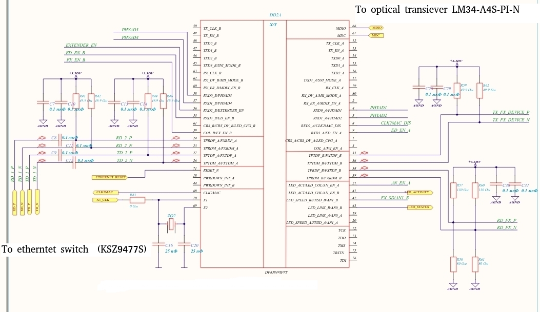
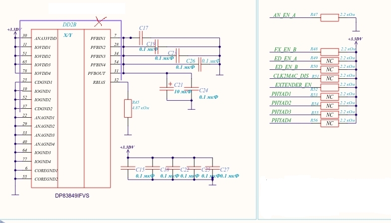
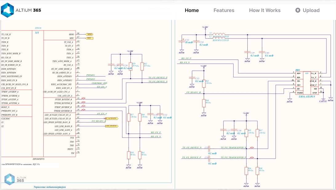
  • Thank you for the response! I've attached the schematic files. I'll also try loopback. Is there some other registers I can use for diagnostics?  

  • Hi Andrey,

    Can you describe the packet loss you are seeing in operation? Do you see packet loss in both directions? Is it a consistent rate of packets across power-ups?

    Regards,
    Justin 

  • Thank you for the reply. It seems that packet loss occurs on TX direction (fiber optics->dp83849ifvs as media converter->ksz9477s switch). Yes, it's approximately 3/4 of traffic lost and the rate is stable (I send through the board 4000 packets per second raw ethernet stream, and only ~1500 packets per second get out of the board). The switch MIB counters show ~1500 good rx packets per second, and the same nomber on TX ports (I have six of them, and situation is the same on all ports). 

  • Hi Andrey,

    Are you able to perform loopback tests on each port to narrow where the packet loss may be introduced?

    Regards,
    Justin 

  • Hi Andrey,

    Have you resolved the issues above? I haven't heard any update and will close the thread if so. 

    Regards,

    Justin 

  • Hi. Sorry for the late response, I've been busy working on other projects... Unfortuantelly I have not solve the problem yet, but I read all the registers of DP83849IFVS and noticed something strange.

    BMCR - 0x2100 (Auto-neg off, 100Mbps, full-duplex) so this is OK on all ports

    BMSR - 0x784d (Auto-neg off, 100Mbps, full-duplex) so this is OK on all ports

    BUT PHYSTS - 0x100 on A ports (copper mode), and 0x14b on B ports (fiber mode). So as far as I understand it shows that there is no link on port A, 10 Mbps on port B, half-duplex on both ports, loopback enabled on port B (I didn't do it), Remote Fault On port B, New Link Code Word on both ports while auto-neg is off. Also some registers like MICR, RECR and others are not readable - mdio driver returns error. Why PHYSTS  readings are so strange?

    Also I should add that when we first power up the board (which has 3 DP83849IFVS devices and AR8035 device on one MDIO bus which are controlled by AM335x SoC), accidentally at first one of   DP83849IFVS  had the same PHYAD as AR8035 device, so they might have been transmitting simultaneously. Can that fact damage the device? As far as I understand MDIO pin on all devices should be open-drain, so nothing bad could happen. Is MDIO pin open-drain or push-pull on DP83849IFVS and AM335x SoC? Thanks a lot!

  • Thank you for the reply. Sorry for the late response, I've been busy working on other projects... I hadn't been able to solve the problen yet. But I read all the registers of DP83849IFVS and noticed something strange:

    BMCR - 0x2100 on all ports - Auto-neg is off, forced mode, 100Mbps, full-duplex, loopback disabled, so this is OK

    BMSR - 0x784d on all ports - Auto-neg is off, forced mode, 100Mbps, full-duplex, loopback disabled, so this is OK

    BUT! PHYSTS - 0x100 on ports A (copper mode), and 0x14b on ports B (fiber mode), as far as I understood it shows that there is no valid link on port A, 10 Mbps speed on ports B, half-duplex on both ports, loopback enabled on port B (I didn't do it), Remote Fault indication on port B, New Link Code Word detected (though auto-neg should be turned off). Why the readings are so strange? They didn't correspond to BMCR and BMSR registers. By the way the readings are the same on all devices (we have three of them on the board). Also some registers, like RECR, MICR etc. are not readable - the mdio driver return an error. 

    Also I should add that at first when we applied the power supply, accidentally two of the devices had been having the same PHYADs for some period of time (on the MDIO bus we have 3 DP83849IFVS, one AR8035 PHY and AM335x SoC acting as the master, so one of the DP83849IFVS and AR8035 had the same ID), so they may have been transmitting simultaneously. Could that fact damage one of the devices?  As far as I understand if the MDIO pin is open-drain (not push-pull) nothing bad can happen. Is MDIO pin on DP83849IFVS and AM335x devices is open-drain or push-pull? I'll try loopback test next. Thanks!

  • Sorry for the duplicate, the reply didn't show up at first.

  • And also if the registers of the IC device are still readable (but some aren't) does it mean that the device are not damaged and fully operational?

  • Hi Andrey,

    Do you have a 1.5kohm pull-up resistor connected to the MDIO pin? 

    The fact some registers are readable and some are not shows there is some issue with MDC/MDIO communication. The PHY is still able to establish link and reflect the auto-negotiation strap settings so it is operational but I cannot say if no damage has occurred. 

    I would not expect only some registers to be affected by some damage to the device though. Can you explain how you rectified the PHY ID issue? What tool are you using to communicate with the PHY? I suspect that the PHYSTS register read is not the true value of the bits in the registers but some intermediate between the good reads and bad reads. 

    Regards,
    Justin 

  • Hi, thank you for the response. I've rectified the PHY ID issue by changing strapping resistors to set approptiate PHY IDs - 0,1,2,3,8,9 for three DP83849IFVS and 4 for AR8035 PHY. To communicate on MDIO bus I'm using u-boot 2020.07 (command mdio read <phyid> <reg>;   mdio write <phyid> <reg>;). I have even two pull-up resistors on MDIO pin - one is 1.5 kOhm to 3.3V2 on my board and the other is 4.7 kOhm to 3.3V1 on SOM where AM335x SoC is installed which is driving MDIO bus, 3.3V2 and 3.3V1 are from different voltage sources - I think that is allright, nothing bad can happen. Am I right or should I remove one of the resistors? If yes then  which one? By the way I can analyze MDIO bus with oscilloscope, so I will try to get PHYSTS register right on the bus and I will keep you posted. Also I should notice that AR8035 PHY (which has 4 PHYID) for some reason doesn't respond to MDIO commands at all, but maybe it doesn't matter. 

  • Hi Andrey,

    Are you making sure that you are accessing the correct register by considering if the u-boot tool uses hexidecimal or decimal formats? I ask because PHYSTS is register 0x10h which may be the first case where hexidecimal and decimal incompatibility may arise.

    I am also unsure about the AR8035 register access, but also points to some issue in reading registers on other PHYs as well. 

    Regards,
    Justin 

  • Hi Justin. When I use u-boot mdio read/write command I convert hexidecimal format of register address from the datasheet to deciamal format. So for PHYSTS register (with hexidecimal address 0x10h) I'd use "=>mdio read 0 16". By the way I didn't find the direct instruction what format to use, but according to "=>mdio" output it should be 0x10 for hexidecimal format and 10 for decimal format. 

  • I've conducted a loopback test on port A (let me recall that I have the following configuration KSZ9477S <-> DP83849IFVS(port A - copper mode) <-> DP83849IFVS(port B - fiber mode)<-> fiber optic transiever LM43-A3S-PI-N). I turned on loopback on port A (so data should travel from fiber transiever to the IC and then right back). I did it with the following command "mdio write 0 0 0x6100". The loopback seemed to start working. And I've got the "reflected" traffic and it already had packet loss - I got ~1940 pps out of 4000 pps raw ethernet stream. The numbers are the same for all ports. So, now, at least I know where the problem starts. Meybe something wrong with my fiber transeiver power supply or IC power supply....

  • The power supply is OK. 3.18V no ripple. Clock is OK eather - amplitude is ~3.2V, 25.01... MHz, fronts are sharp... I'll investigate 100BASE-FX signalling. By the way what amplitude is it should be approximatelly? +-2.5 V? 

  • Hi Andrey,

    Regarding MDC/MDIO communication, it looks like you register addressing is correct, so I am not sure what is causing the corruption of some register reads. 

    When conducting the loopback test, you want to test the PMD loopback, since you are receiving data along the Copper/Fiber interface and sending it back to a link partner. You can use register 0x17[8]. Please let me know whether you are able to see error free data in the loopback either port in this mode. 

    Regards,
    Justin

  • Hi Justin,

    I've conducted PMD loopback test on port B (which is connected to fiber optics) with help of command "mdio write 1 0x17 0x5c1". And the test shows error - the same packet loss - only ~1850 packets got back out of 4000. Maybe something wrong with my schematic between IC and fiber optic, I'll attach the scheme... Meanwhile I'll check if my power supply gets to all necesary pins of IC. Thanks!

  • By the way I've got 4.45 kOhm instead of 4.47 kOhm on RBIAS pin. Is it safe? What this resistor is doing actually?

  • Hi Andrey,

    The RBIAS pin is used to set the internal reference nodes for the output transmitter. It is important that this resistor is carefully selected. Can you please try a 4.47kohm 1% tolerance resistor for the RBIAS pin?

    Regards,
    Justin 

  • Hi, Justin.

    Ok, I'll try to do that. Also maybe it'd be usefull to perform a BIST test, though I didn't get completely how it works and what it shows. Does this test checks all digital nodes (modules) of the IC? Thanks.

  • Hi Andrey,

    The BIST test will test the internal data-path through the MAC interface to the analog PMA transmitter and back. In media-converter mode the BIST mode will not cover the same data blocks.

    Regards,
    Justin 

  • Hi Justin,

    You said, data-path through the MAC interface to the analog PMA transmitter, including PMA transmitter itself?  "In media-converter mode the BIST mode will not cover the same data blocks." - didn't get what you mean... Can I test port A and port B separately with BIST test? Thanks a lot!

  • Hi Andrey, 

    Sorry for the confusion. I was mistaken when I said that BIST would not cover the PHY in media converter mode. If you test Port A and Port B separately, this will cover each port. It works by generating packets through the PRBS and looping them through the PHY to the PRBS checker. 

    Regards,
    Justin