This thread has been locked.

If you have a related question, please click the "Ask a related question" button in the top right corner. The newly created question will be automatically linked to this question.

DS90UB960-Q1: DS90UB960-Q1: pattern generator cannot work

Part Number: DS90UB960-Q1

Hi, 

I  want to  configure CSI Port 0 to generate a test pattern,but  it  cannot work  well,I see the py script

# Set CSI Timing parameters for 400Mbps operation (both ports)
board.Ind_Acc_Write(0x0, 0x40, [0x83, 0x8D, 0x87, 0x87, 0x83, 0x86, 0x84, 0x86, 0x84], 9)
board.Ind_Acc_Write(0x0, 0x60, [0x83, 0x8D, 0x87, 0x87, 0x83, 0x86, 0x84, 0x86, 0x84], 9)

      what's meaning of this。

how  can i  do it  use  i2cset?

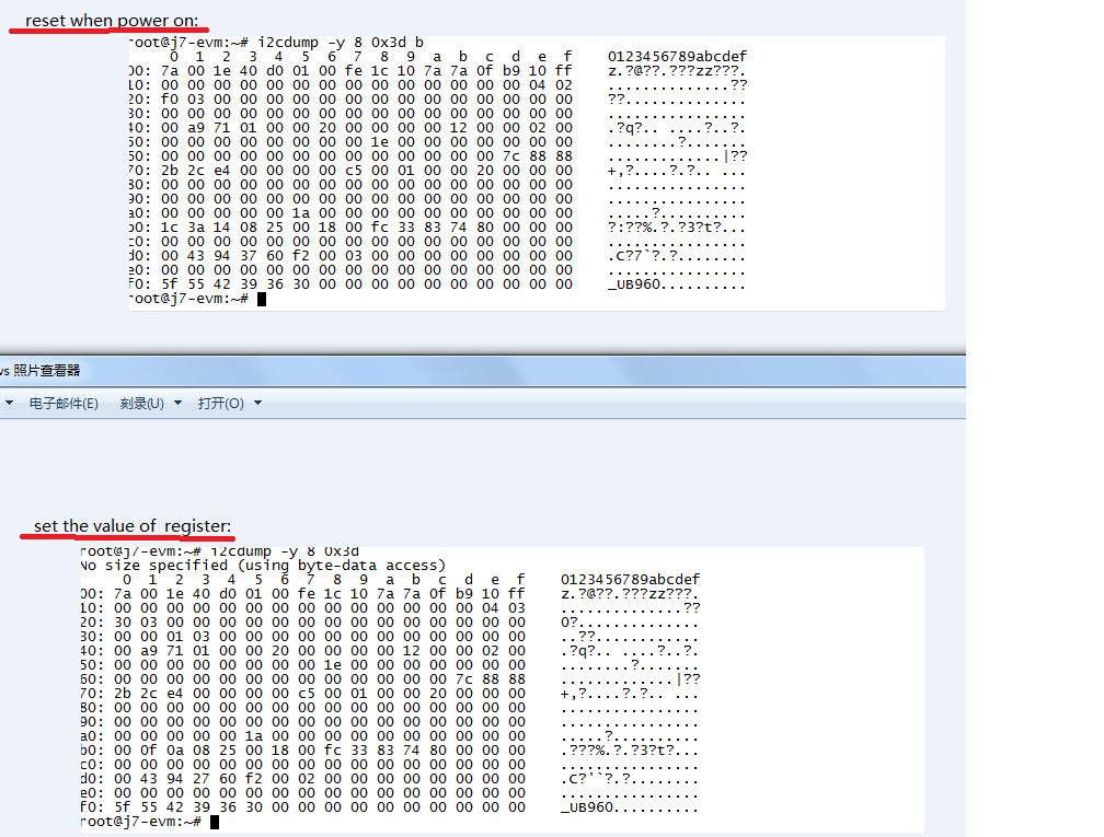
My setting  is like the follow:

i2cset -y 8 0x3d 0x01 0x01

i2cset -y 8 0x3d 0x1F 0x03

# Set CSI Timing parameters for 400Mbps operation (both ports)
#board.Ind_Acc_Write(0x0, 0x40, [0x83, 0x8D, 0x87, 0x87, 0x83, 0x86, 0x84, 0x86, 0x84], 9)
#board.Ind_Acc_Write(0x0, 0x60, [0x83, 0x8D, 0x87, 0x87, 0x83, 0x86, 0x84, 0x86, 0x84], 9)
#
# CSI sel and CSI enable
i2cset -y 8 0x3d 0x32 0x01
msleep 500
i2cset -y 8 0x3d 0x33 0x03
msleep 500

# enable pat gen
i2cset -y 8 0x3d 0xB0 0x00
i2cset -y 8 0x3d 0xB1 0x01
i2cset -y 8 0x3d 0xB2 0x01

i2cset -y 8 0x3d 0xB1 0x02
i2cset -y 8 0x3d 0xB2 0x33

i2cset -y 8 0x3d 0xB1 0x03
i2cset -y 8 0x3d 0xB2 0x24

i2cset -y 8 0x3d 0xB1 0x04
i2cset -y 8 0x3d 0xB2 0x16

i2cset -y 8 0x3d 0xB1 0x05
i2cset -y 8 0x3d 0xB2 0x80

i2cset -y 8 0x3d 0xB1 0x06
i2cset -y 8 0x3d 0xB2 0x02

i2cset -y 8 0x3d 0xB1 0x07
i2cset -y 8 0x3d 0xB2 0xD0

i2cset -y 8 0x3d 0xB1 0x08
i2cset -y 8 0x3d 0xB2 0x04

i2cset -y 8 0x3d 0xB1 0x09
i2cset -y 8 0x3d 0xB2 0x38

i2cset -y 8 0x3d 0xB1 0x0a
i2cset -y 8 0x3d 0xB2 0x04

i2cset -y 8 0x3d 0xB1 0x0b
i2cset -y 8 0x3d 0xB2 0x65

i2cset -y 8 0x3d 0xB1 0x0c
i2cset -y 8 0x3d 0xB2 0x05

i2cset -y 8 0x3d 0xB1 0x0d
i2cset -y 8 0x3d 0xB2 0xc9

i2cset -y 8 0x3d 0xB1 0x0E
i2cset -y 8 0x3d 0xB2 0x21

i2cset -y 8 0x3d 0xB1 0x0F
i2cset -y 8 0x3d 0xB2 0x0A

  • The same work with me.

  • Hello,

    What kind of errors are you seeing on the SoC? Are you receiving packets at all? Please send me the intended video parameters (frame rate, resolution, data type) for the pattern so I can check your register configuration.

    If you are using 400 Mbps, make sure to configure the timing parameters for the port per section 7.4.19 of the datasheet.

    Verify that you have successfully established communication between the SoC and 960. Also verify that you are setting up the pattern generator tx correctly:

    Register 0x20 -> 0x30

    Register 0x1F -> 0x03 (if you’re using 400 Mbps)

    Register 0x32 -> 0x01

    Regards,

    Carrie

  • I  do it in  the tda4evm  board,the register like this :


    my setting is :

    i2cset -y 8 0x3d 0x01 0x01
    msleep 500
    # Set CSI_TX_SPEED to select 400Mbps
    i2cset -y 8 0x3d 0x1F 0x03
    msleep 500

    i2cset -y 8 0x3d 0xB0 0x02
    i2cset -y 8 0x3d 0xB1 0x40
    i2cset -y 8 0x3d 0xB2 0x83
    i2cset -y 8 0x3d 0xB2 0x8D
    i2cset -y 8 0x3d 0xB2 0x87
    i2cset -y 8 0x3d 0xB2 0x87
    i2cset -y 8 0x3d 0xB2 0x83
    i2cset -y 8 0x3d 0xB2 0x86
    i2cset -y 8 0x3d 0xB2 0x84
    i2cset -y 8 0x3d 0xB2 0x86
    i2cset -y 8 0x3d 0xB2 0x84
    # CSI sel and CSI enable
    i2cset -y 8 0x3d 0x32 0x01
    msleep 500
    i2cset -y 8 0x3d 0x33 0x03
    msleep 500
    i2cset -y 8 0x3d 0xB0 0x00
    i2cset -y 8 0x3d 0xB1 0x01
    i2cset -y 8 0x3d 0xB2 0x01
    i2cset -y 8 0x3d 0xB1 0x02
    i2cset -y 8 0x3d 0xB2 0x33
    i2cset -y 8 0x3d 0xB1 0x03
    i2cset -y 8 0x3d 0xB2 0x24
    i2cset -y 8 0x3d 0xB1 0x04
    i2cset -y 8 0x3d 0xB2 0x16
    i2cset -y 8 0x3d 0xB1 0x05
    i2cset -y 8 0x3d 0xB2 0x80
    i2cset -y 8 0x3d 0xB1 0x06
    i2cset -y 8 0x3d 0xB2 0x02
    i2cset -y 8 0x3d 0xB1 0x07
    i2cset -y 8 0x3d 0xB2 0xD0
    i2cset -y 8 0x3d 0xB1 0x08
    i2cset -y 8 0x3d 0xB2 0x04
    i2cset -y 8 0x3d 0xB1 0x09
    i2cset -y 8 0x3d 0xB2 0x38
    i2cset -y 8 0x3d 0xB1 0x0a
    i2cset -y 8 0x3d 0xB2 0x04
    i2cset -y 8 0x3d 0xB1 0x0b
    i2cset -y 8 0x3d 0xB2 0x65
    i2cset -y 8 0x3d 0xB1 0x0c
    i2cset -y 8 0x3d 0xB2 0x05
    i2cset -y 8 0x3d 0xB1 0x0d
    i2cset -y 8 0x3d 0xB2 0xc9
    i2cset -y 8 0x3d 0xB1 0x0E
    i2cset -y 8 0x3d 0xB2 0x21
    i2cset -y 8 0x3d 0xB1 0x0F
    i2cset -y 8 0x3d 0xB2 0x0A

    I checkout the value of the register "0x35" is still 0,so  I think it does not work well.

    what's wrong with me?


  • Hello Zhangsc,

    We will look into these register settings and plan to follow up on Monday 

    Best Regards,

    Casey 

  • Hello Zhangsc,

    Register 0x35 only indicates valid data on the TX port if there is incoming serializer data. It does not get set during successful pattern generation.


    Register 0x02 should be set to 0x3E, which will enable output without active receiver lock.

    The value in register 0x04 indicates that there isn’t a valid refclk provided to the REFCLK pin (pin 5). A 25 MHz LVCMOS-level oscillator (100 ppm) is recommended. The refclk has to be detected before CSI-2 output can be produced.

    Set register 0x20 to 0xF0 instead of 0x30 to disable all RX ports.

    Make sure that you’re selecting a TX port using register 0x32 (CSI_PORT_SEL) before enabling or configuring that port.


    Can you please send me the pattern parameters (frame rate, data type, resolution, etc) so I can verify register configuration for your pattern generation?

    Regards,

    Carrie

  • HI,

    I want to TDA4 Fusion Application Board_spruii   Generate pattern

    (

    # 1920*1080 @ 30 fps 
    # 4 x lane 800Mbps/lane 
    # Data Type: YUV422 10-bit  or RGB888  24bit

    )

    1,can you offer the register config.

    2,how can i checkout  pattern generation work success。

    Thanks

  • Hello Zhangsc,

    Based on these settings (data type RGB888) your pattern generator registers look fine. Just change the line period to 0x0B92 (2,962). If your CSI-2 TX data rate is 800 Mbps, set CSI_PLL_CTL[1:0] to 0b10 and reset the CSI-2 timing parameters. The default values for these parameters are compliant with MIPI standards for 800 and 1600 Mbps.

    To verify successful pattern generation, a CSI-2 analyzer can be connected to the deserializer.

    Regards,

    Carrie

  • The value in register 0x04  is 0xD0, My refclk is right?

    BIT 4 is 1

    1 : REFCLK frequency between 12 MHz and 64 MHz

  • Hello Zhangsc,

    For 960 the REFCLK should be between 23-26MHz. You can check the measured frequency in register 0xA5. Can you verify that it meets those frequency requirements?

    Best Regards,

    Casey