Other Parts Discussed in Thread: TMDS181
I have the same symptom as this link, which was taken offline.
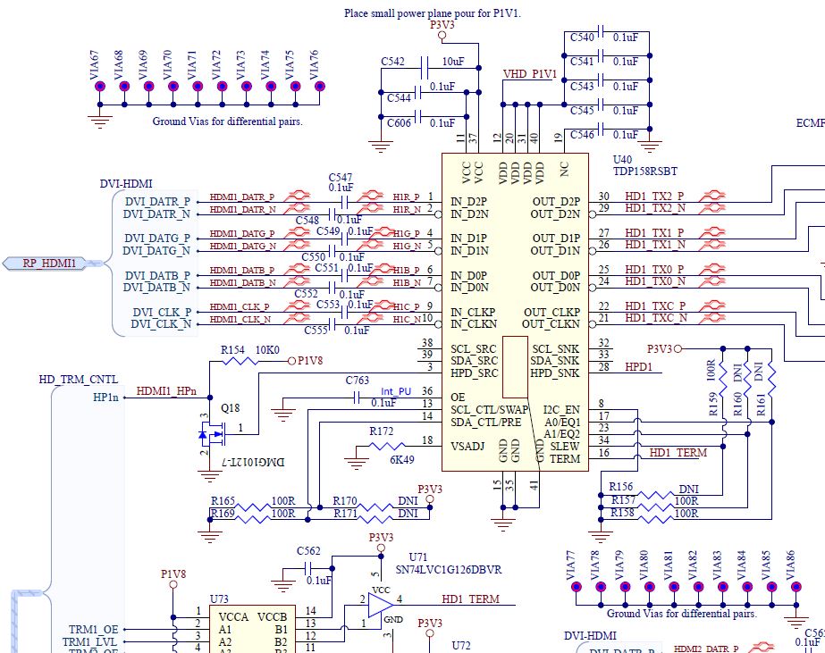
Using Pin-Strap mode only, the monitor is present, but no video passes from the input to the output of the tdp158.
A 0.1uF cap is connected to the OE pin, using the internal pull up.
HPD_SNK is high.