Other Parts Discussed in Thread: ALP, USB2ANY
Hi All,
I have designed an impedance controlled PCB containing two DS90UB953s and a DS90UB954 as an alternative to your EVM that isn't compatible with our imaging modules. I am using UMCC connectors and prewired UMCC coax (1/37mm dia 50 ohm coax a few inches long) to connect the 953s & 954.
Of the two 953's, one appears to have a broken ferrite because it has no DC voltage coming through the coax, but the other appears functional. I am using RX1 on the 954 to connect with it.
I have the wrong bias resistors on the 954 mode pin (a single 10K to ground) that sets it for CSI-2 non-synchronous mode, when I really wanted CSI-2 synchronous back channel. But I am assuming I can simply change register 0x58 to get into sync mode.
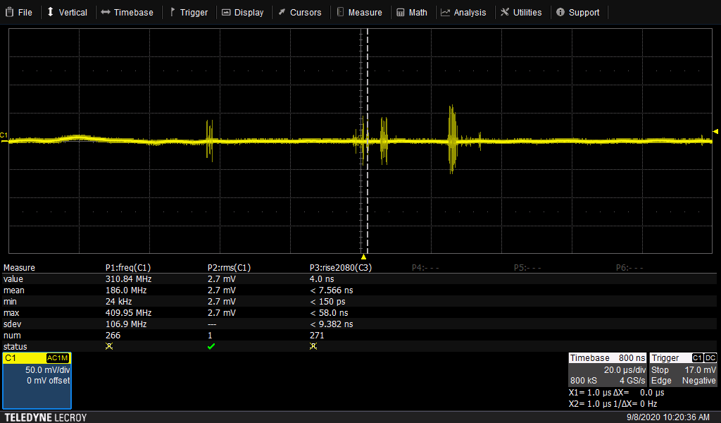
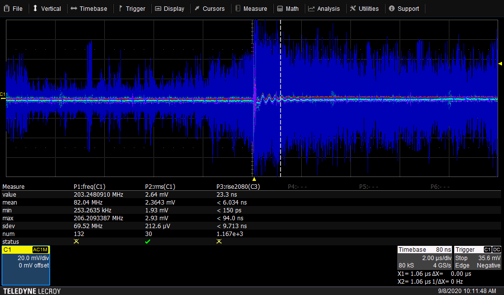
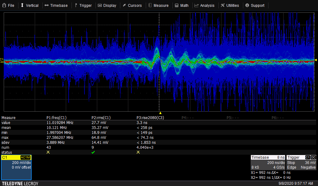
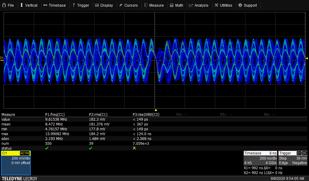
I can communicate with the 954 at address 0x60 as expected, but never see the LINK signal high. I am using a 24 MHz reference clock (oscillator), and see 24 MHz on the 954's XOUT signal. The frequency measurement register (xA5) consistently shows 23 MHz. The link frequency (0x4F:50) always shows 0.
Both 953's are strapped for address 0x30 but at 1.8V (IDX has a 40.2K pull-down to ground), and mode is connected to ground with a 10.0K, which as I understand it, enables the synchronous back channel. I assume I can change a register in the 953 to set the I2C bus for 3.3V operation.
I've tried setting register 0x4C to x12 (select P1), then setting 0x58 to 0x1E (BC on with CRC at 50 MHz) and 0x6D to 4 (coax mode), but none of these changes have made any difference to the LOCK state.
Can you point me in the correct direction to debug the link?
Thanks,
Scott