This thread has been locked.

If you have a related question, please click the "Ask a related question" button in the top right corner. The newly created question will be automatically linked to this question.

DS90UB954-Q1: No 954/953 Link

Part Number: DS90UB954-Q1
Other Parts Discussed in Thread: ALP, USB2ANY

Hi All,

I have designed an impedance controlled PCB containing two DS90UB953s and a DS90UB954 as an alternative to your EVM that isn't compatible with our imaging modules.  I am using UMCC connectors and prewired UMCC coax (1/37mm dia 50 ohm coax a few inches long) to connect the 953s & 954.

Of the two 953's, one appears to have a broken ferrite because it has no DC voltage coming through the coax, but the other appears functional.  I am using RX1 on the 954 to connect with it.

I have the wrong bias resistors on the 954 mode pin (a single 10K to ground) that sets it for CSI-2 non-synchronous mode, when I really wanted CSI-2 synchronous back channel.  But I am assuming I can simply change register 0x58 to get into sync mode.

I can communicate with the 954 at address 0x60 as expected, but never see the LINK signal high.  I am using a 24 MHz reference clock (oscillator), and see 24 MHz on the 954's XOUT signal.  The frequency measurement register (xA5) consistently shows 23 MHz.  The link frequency (0x4F:50) always shows 0.

Both 953's are strapped for address 0x30 but at 1.8V (IDX has a 40.2K pull-down to ground), and mode is connected to ground with a 10.0K, which as I understand it, enables the synchronous back channel.  I assume I can change a register in the 953 to set the I2C bus for 3.3V operation.

I've tried setting register 0x4C to x12 (select P1), then setting 0x58 to 0x1E (BC on with CRC at 50 MHz) and 0x6D to 4 (coax mode), but none of these changes have made any difference to the LOCK state.

Can you point me in the correct direction to debug the link?

Thanks,

Scott

  • Hello Scott,

    Can you post your schematics for both sides here so we can review the connections? Seems like maybe a schematic connection issue 

    Best Regards,

    Casey 

  • Hi Casey,

    I've attached the schematic.

    Thanks,

    AJ-02-00734-1 SCH.pdfScott

  • Hi Scott, 

    For a schematic review, I will need a few days to get back to you on this. Please give me until COB Monday. 

    Thanks, 
    Sally 

  • Hi Scott, 

    Can you probe the DC voltage on the 953 at all the rails to make sure it is meeting the minimum voltage? Also do the same for the 954. Please make sure you probe after the ferrite bead - so closer to the pin.

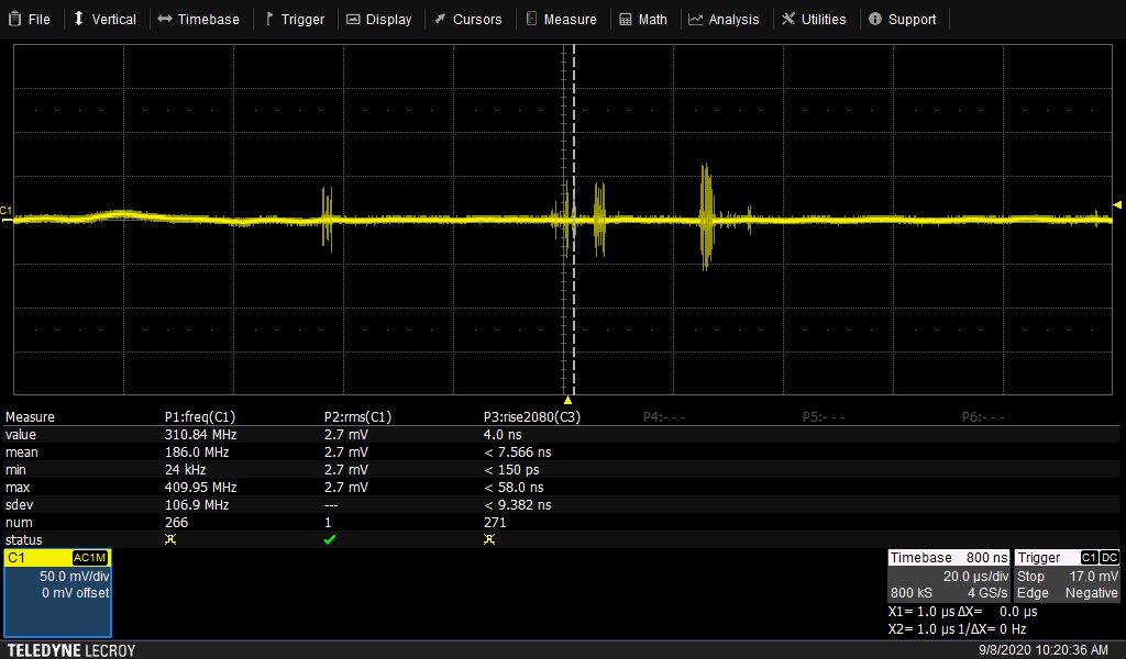
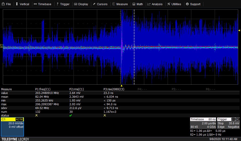
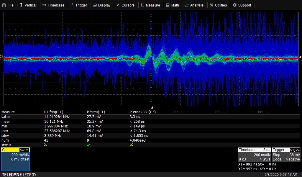
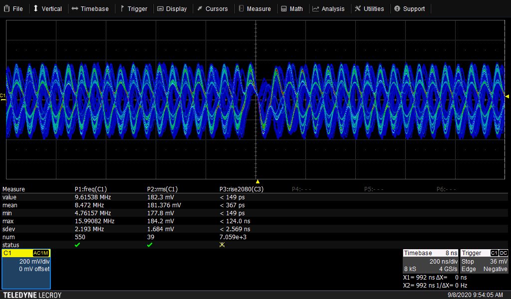
    Can you also probe the supply noise after the PoC before the input to the voltage regulator? The differential supply noise should be less than 25 mV. What is the pulse amplitude and the slew rate of the pulse amplitude? Also please probe supply noise at RIN+ when 954 is powered down. The supply noise should be less than 10 mV. 

    For synchronous mode, is it possible for you disconnect the oscillator on the 953? Im not sure if it's currently populated on your board. 

    Please also check for line fault in register 0x4E on the 954. 

    Yes you can change the strap settings via register programming. 

    Have you already verified the power sequencing diagram according to the d/s?

    Does your oscillator connected to the 954 meet Table 3 specifications in the d/s? 

    Can you run BIST ? 

    That link has a BIST script.

    Can you run MAP in the ALP GUI on the 954? 

  • Hi Sally,

    Sorry for the long delay, off on other projects.

    All the DC voltages are right on the mark.  The 953 supply measures 1.81V, the 954 supplies    measures 1.82 and 3.31V.  I've taken several scope traces of random impulse type noise on the supplies.

    The 954's oscillator is a Diodes Inc FJ2400002 1.8V oscillator and meets all table 3 specs.

    Since the 1.1V supply is internally generated (VDD_SEL=0), this isn't an issue, right?

    I haven't been able to run BIST with the connection errors.

    Thanks,

    Scott

  • Hi Scott, 

    Its good that you verified the DC power of those supplies, but we also need to check the noise requirements. 

    There are two PoC noise requirements for the SER and DES:

    1.Requirement on the serializer side (Vpoc noise)
    Methodology:
    –Have the whole system (imager, serializer, and deserializer) running
    –The imager switching can introduce Vpoc pulse to the system
    –Measure the Vpoc noise at the input side of the DC-DC regulator on the serializer board
    •Set the scope to 0 to 50MHz bandwidth
    –Account for noise floor in the probe (Noise = measured noise – noise floor)
    Where to Probe:
    Probe after the PoC filter before the input of the regulator

    2. Requirement on the deserializer side (Rin+ noise)

    Methodology:
    –Connect the deserializer and serializer using a cable, turn on the power supply
    –Turn off the deserializer and serializer (by pulling the PDB low)
    –Measure the noise at the Rin+ pin of the deserializer
    •Set the scope to 0 to 50MHz bandwidth
    •Use a short probing tip for ground
    •Account for noise floor in the probe (Noise = measured noise – noise floor)
    Where to probe: Probe the Rin+ pin, probing at the AC coupling cap.
    What values are you getting? 
  • Hi Sally,

    On the serializer side at the regulator input I measure 200-300 uV (rms) of noise after subtracting the 400-600 uV background noise value.  Its quite a noisy measurement as I am my scope's vertical resolution limit (10 mV scale).

    I am not able to communicate with the image sensor on the serializer side of the system so I am unable to make them stream data to contribute to system noise.  Without them, I measure 2.2mV of rms noise after subtracting the 800-900 uV of noise floor.

    When you mentioned grounding PDB on both ends, I noticed that I have not connected PDB on the serializers and the DS says they are pulled to the inactive state (low) with an internal 1M resistor, so I tried connecting these pins to 1.8V.  Unfortunately this didn't seem to make any difference.  I still read 0xD3 from status register 4 on the 954.

    Thanks,

    Scott

  • Hi Scott, 

    It seems like the noise is ok, but just to isolate further, is it possible to power the SER independently? Do you guys have a way of supplying external power to the SER?

    Thanks, 
    Sally 

  • Hi Sally,

    Referring to my original schematic, do you mean to isolate power by removing FB1 (FB2 or FB3) and wiring VLINK to +5 so the link isn't supplying the SER side power?  Sure I can do that.  Or do you mean supply power from some other source, such as a bench supply?  I can also do that.

    I just want to confirm that there are no I2C commands I need to send to the 954 establish the link with the 953s.

    Thanks,

    Scott

  • Hi Scott, 

    The first option: removing FB1 (FB2 or FB3) and wiring VLINK to +5 so the link isn't supplying the SER side power. 
    You're correct, there shouldn't be any I2C commands that you need to send for establishing link. Just want to make sure you are strapped in the right mode. Looking back at your schematic, I see that you have 10kohm pull up/down resistors on the mode/idx pins for the 954. I initially assumed these were place holders, so I must ask if you ever updated the values. 

    Thanks, 
    Sally 

  • Hi Sally,

    I rechecked the population options this morning and all are correct except the 954 mode pin is strapped for CSI-2 non-sync back channel.  I will move the 10K resistor from R53 to R54 which will strap it for RAW10 mode which it what we are transmitting.

    If that doesn't help, I'll remove FB1 and power the system from a 5V supply.

    I'll let you know what happens.

    Thanks,

    Scott

  • Hi Sally,

    I ran the power supply isolation experiment by removing FB1 and wiring the 5V supply from P3.1 to the junction of FB21 and L10 (so L10 is included in the voltage regulator input filter network.

    Nothing has changed.  TP19 (PASS) and TP20 (LOCK) are still both low.  TP25 is clocking at 24 MHz (my reference oscillator frequency).  Reading status register 4 still reports 0xB3 confirming pass & lock are both false.

    Best,

    Scott

  • Hi Scott, 

    Can you also remove FB25? Did you also fix the mode strapping?


  • Hi Sally,

    Good catch.  Yesterday I fixed the strapping so the 954 is in mode 3 by setting R54 to 10K and removing R53.

    I removed FB25 but got the same result, reg 4 still reads 0xB3 and LOCK and PASS are low.

    Thanks,

    Scott

  • Hi Scott, 

    What is register 0x4D reading? Do you have I2C communications? What is the parity error count on ALP?

  • Hi Sally,

    0x4D reads 0.  I am communicating with the 954.  I assume there must be a link before I can communicate with the 953 through the 954.  The parity error count (reg x55) is zero.

    Best,

    Scott

  • Hi Scott, 

    Can you try running MAP in the ALP tool and let me know if there are any bars that are green? I want to know if the link is just not adapting to the correct settings or not.

    Thanks, 
    Sally 

  • Hi Sally,

    Sorry for the long delay, I've been off on other projects.

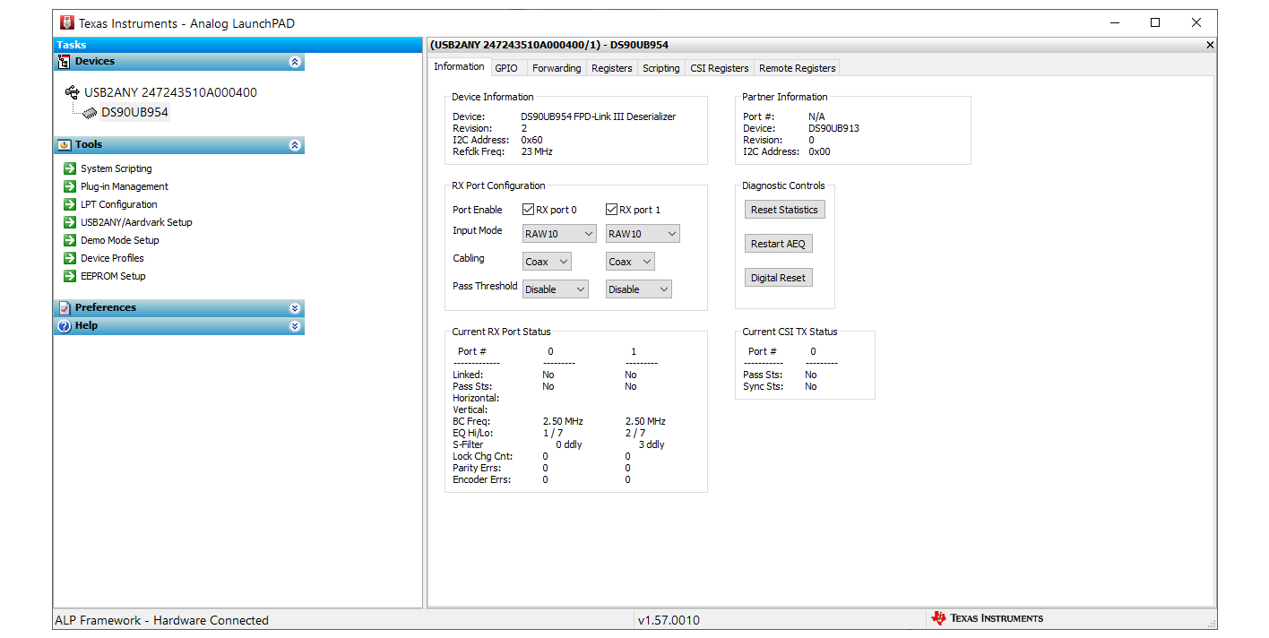
    So I have downloaded ALP and the profile updater but when I launch ALP, it hangs.  Also I see no operating instructions anywhere, can you point me to them?

    Thanks,

    Scott

  • Hi Scott, 


    Starting from page 15, there are instructions on using ALP. You may also  have to update the firmware on the USB2ANY device using the USB2ANY app. If it hangs, usually it's an indication the 954 SCL/SDA lines are having communication errors - perhaps the wrong SCL/SDA lines connected or there is no power. 

    See page 13 on how to connect the USB2ANY. 

  • Hi Sally,

    Our USB2ANY dongle arrived today.  I got it hooked up and so far all it's done is confirm there's no link between the 954 and 953s.  Also, how do I "run MAP"?

    Thanks,

    Scott

  • Hi Scott, 

    To run MAP, refer to this appnote https://www.ti.com/lit/an/snla301/snla301.pdf?ts=1595022679737&ref_url=https%253A%252F%252Fwww.ti.com%252Fproduct%252FDS90UB954-Q1

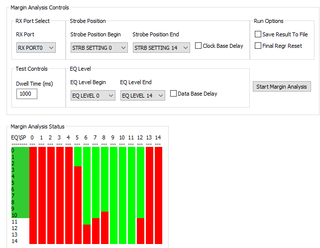
    1. Run MAP in ALP. Let the scan start at 0, RX0 selected, and Final Regr Reset unchecked.

    1. Get the green/red bars filled
    2. Soft reset (no registers included)
    3. Program min/max EQ (0 – 14) 0xD5 = 0xE0 (set it at max to account for cable aging)
    4. Program min/max Sfilter (6-12) 0x41 = 0xC6
    5. Enable Adaptive EQ. 0xD4 = 0x01  
    6. AEQ error control checks all errors (clk errors, packet encoding errors, parity errors). Enable sfilter adaption with AEQ. 0x42 = 71
    7. Restart AEQ. 0xD2[3] =1

    * I am showing you an example of a MAP output and the values for EQ & Sfilter. Your's will vary depending on your output. 

  • Hi Sally,

    How do I get to the screen showing the MAP controls that you've shown?  I assumed it was a script, but don't see any scripts remotely related to MAP and the application note only discusses the theory behind the MAP analysis, not actually how to run the analysis.

    Thanks,

    Scott

  • If you connect directly to the 953, are you able to communicate with that device ok? Is the 953 being powered? I am not sure why, but your 954 profile seems to be missing the MAP tab. I am attaching the correct profile which contains a MAP tab DS90UB954.zip

  • Hi Sally,

    Oh, I am connected to the 954.  By this I mean the USB2ANY is wired to the 954's I2C signals.  Should I be connecting to one of the 953's instead?  If so, which one or doesn't it matter?

    Thanks,

    Scott

  • Please connect to the 954 because MAP is run on the DES. I wanted to ask if when you connected to SER are you able to communicate with that device. I am just checking to make sure that the SER is powered and can read it's own device ID. 

    -sally 

  • Hi Sally,

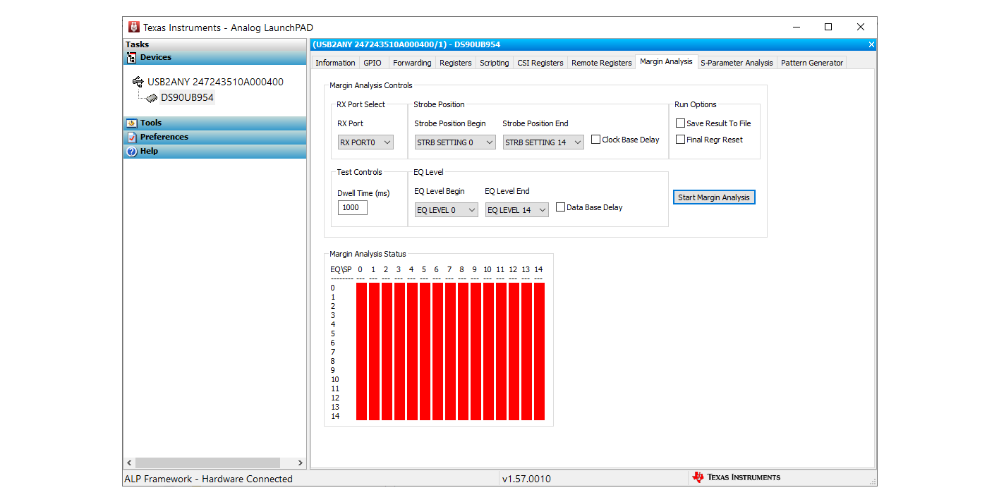
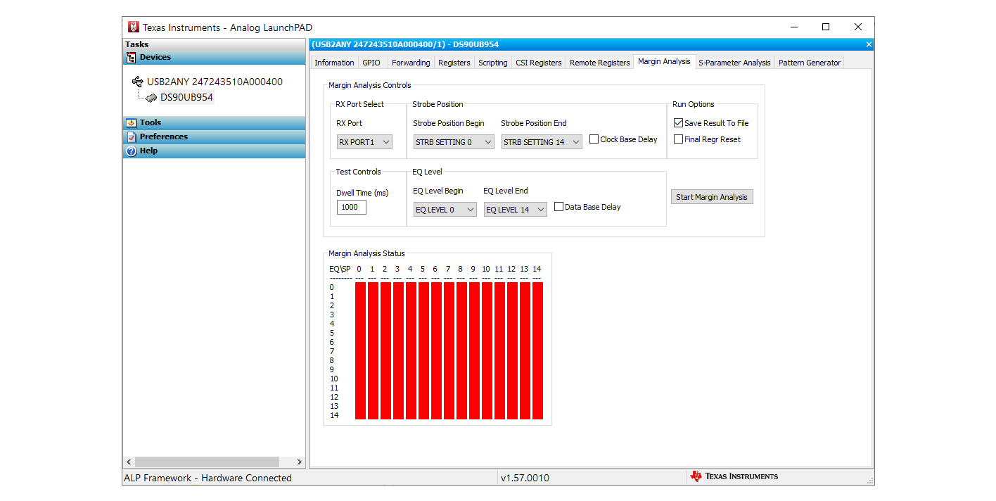
    I tried copying the profile you sent to the ALP profiles directory, but this corrupted the program.  So I downloaded and installed another copy.  The new installation is now showing the additional tabs, including Margin analysis.

    I set the parameters as you've shown and ran MAP on both receive ports.  All blocks are red!~  How to I proceed?

    One thing I haven't mentioned that I'm wondering about is the selection of coax cable.  I am currently using 4" UMCC cable assembles, with 0.81mm 50-ohm coax.  I am wondering if the link is expecting longer cables?

    Thanks,

    Scott

  • Hey Scott, 

    Can we take this offline? I want to compare channel specs because I am wondering if the cables are causing bad link. Please email me s-cheung@ti.com

    Thanks, 
    Sally