This thread has been locked.

If you have a related question, please click the "Ask a related question" button in the top right corner. The newly created question will be automatically linked to this question.

DS90UB933-Q1: I2C issue in 933

Part Number: DS90UB933-Q1

Hi expert,

customer use OV9284 + FH8310 +933 in their project, the FH8310 is ISP.

we have below problem:

1. they build 20 pcs board, found the frame rate is not stable. Normally it is 30fps, but some board only 26fps.

2. they use FH8310 to upgrade 933 sofeware by I2C, it found some boards are failed to upgrade.

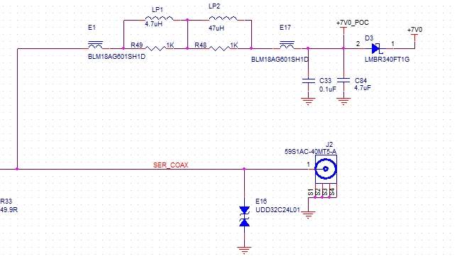
I attached the customer schematic, could you help check and give some suggestions? thanks in advance.

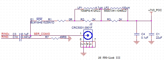
below is POC circuit of 936.

SCHEMATIC1 _ 05-TI933.pdf

  • Hi Betty, 

    What do you mean some boards failed to upgrade? What is the issues with the 933?

    Thanks, 
    SAlly 

  • Hi Sally,

    I use below disgram to describe this problem. they use Fakra cable in this case.

    1. customer measure the frame rate at node 1, it is normal 30fps. In the Derser, they have a GUI to display sensor image. the GUI report the frame rate is 26fps.

    so, customer suspect that there have noise in LVDS signal in the Fakra cable.

    2. The 3 line is show that ISP to write register by I2C diretly, the ISP will sent a group data, then 933 should be return the same data. but ISP find the receive data is not same with sent, so, software upgrade fail.

    3. Since the power supply of whole systemis come from POC, And, there are also power supply and LVDS in fakra cable. Therefore,we suspect maybe the POC circuit have problem, which cause the camera frame rate error and I2C issue.

    please review the customer schematic and POC circuit to check if there are problems. thanks.

  • Hi Betty, 

    The PoC looks fine. I will review the circuit and get back to you by next Monday. 

    Thanks, 
    Sally 

  • Hi Sally,

    Attached customer layout picture and file, please also help to review. thanks.

    HW_C-CAM-IC005A-POWER_PCB_1V0_A-20200807.brd

  • The schematic looks ok. Can you read back these registers to me: 

    0x4D, 0x4E, 0x7A,0x7B 

  • Hi Sally

    two questions:

    1. What are the functions of 0x4d.0x4e.0x7a and 0x7b? I didn't find these register on datasheet.

    2. could you check the layout? I have attached it. we have concern that if signal lines and power lines separately routed

    thanks.

  • Hi Betty, 

    Those registers can be read on the DES. 
    I am not sure how to open that file. I have Altium. 

  • Hi Sally,

    I also attched customer layout picture of POC circuit, please check.

    for registers, please see the below:

    De-ser 936:

    reg

    Abnormal board

    normal board

    0X4D

    33

    3

    0X4E

    E5

    4

    0X7A

    0

    0

    0X7B

    0

    0

     Ser 933:

    reg

    Abnormal 

    Normal

    0X0A

    FF

    0

    0X0B

    FF

    0

    And, customer use external power instead of POC to supply 933, not find the before issue. they have test two boards, the result is same. We suspect it is POC problem.

    Please check customer POC circuit and layout.

  • Hi Betty, 

    it's difficult to see from those snaps shots, so I will ask you: 

    1. Did they route RX+ and RX- with differentially and loosely coupled (S = 3W) 100ohm ±10% traces. Make sure they terminate RX- near the connector and switch RX+ to 50ohm single-ended trace.
    3.Spacing with adjacent ports should be greater than 3-5 times the width of the trace to avoid mutual coupling.
    4.Place the AC coupling caps close to the device pins. Make sure to add anti-pads underneath the AC coupling caps for impedance matching. The footprint for the caps should be coupled with ground.
    5.Place the first PoC inductor/ferrite bead orthogonally to the RX+ traces, barely touching the trace instead of crossing through the trace. Add anti-pads underneath the footprint to ensure consistent impedance. Make sure RX+ traces can carry PoC current without significant temperature rise.
    6. Can they probe their SER board to make sure they are getting the correct voltages at the power pins?
    Thanks 
    Sally 
  • Hi Sally,

    I will feedback to customer.

    one more question. for current POC circuit, if the input is 10V, current need 500mA, does below POC circuit can handle this requirement? and how to select inductor?

  • Hi Betty, 

    I was not able to find the d/s for the ferrite beads, but you should make sure that the saturation current of those parts are above 500 mA. You can follow our "2G" PoC example on which inductor values to use and what the SRF frequencies are. 

    Thanks, 
    Sally