This thread has been locked.

If you have a related question, please click the "Ask a related question" button in the top right corner. The newly created question will be automatically linked to this question.

DP83822I: DP83822I using RMII interface

Part Number: DP83822I
Other Parts Discussed in Thread: AM3352

Hi,

I use AM3352 along with DP83822I on my custom board.
I have a problem with the correct PHY configuration in RMII mode (master mode).
The interface connection and bootstrap configuration are as bellow.
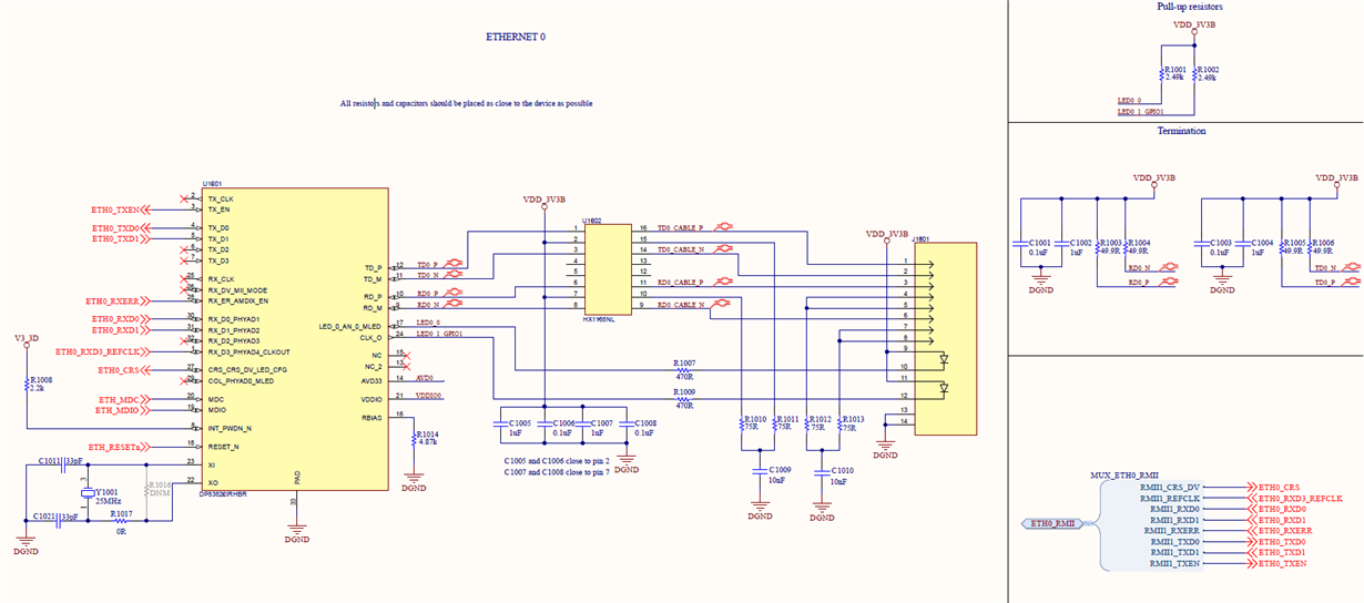

According to this bootstrap configuration, the PHY starts in MII and I use U-boot along with MDIO to write proper values to PHY registers.

I found that I have to write:
0x61 into register 0x17
0x4300 into register 0x462

The sequence is as follows:

mii write 1 0D 1F
mii write 1 0E 462
mii write 1 0D 401F
mii write 1 0E 4300

mii write 1 17 61


The link status and auto-negotiation act properly.
However, I'm not able to send anything and I see overflow detected.
I see big numbers in registers FCSCR and RECR.

Questions:

1) Which registers do I need to configure? (assuming the bootstrap is configured as shown above). Have I missed anything I need to change?

2) How can I find out what is wrong in my configuration?

3) What are the recommended steps to troubleshoot this issue?

/Adam
  • Hi Adam,

    Thanks for providing the schematic and details. Could you kindly provide a read of registers 0x0, 0x1, 0x10, and 0x6E both before and after programming the device for RMII Master mode?

    Thank you,

    Nikhil

  • Hi Nikhil,

    I have a problem to find the 0x6E register. Is this the correct number?
    Finally, I read this register, assuming it's an extended one.

    The values are as follows:

    Before
    0x0 - 0x3100
    0x1 - 0x786D
    0x10 - 0x6915 (first read) / 0x6D15 (subsequent reads)
    0x6E - 0x0 (read as an extended register)

    After
    0x0 - 0x3100
    0x1 - 0x786D
    0x10 - 0x6915 (first read) / 0x6D15 (subsequent reads)
    0x6E - 0x0 (read as an extended register)

    Regards
    Adam

  • Hi Adam,

    Yes 6E is an extended register. However, I was mistaken in which register I asked you to read. Could you provide a read of the strap in registers 0x467 and 0x468? These are extended registers. Are you programming the device after bootup or using only the strap settings?

    Additionally, the register 0x10 value of 6915 and 6D15 tells me there is a polarity swap of the MDI pairs ( Receive on TD and transmit on RD. Can you confirm by reading register 0xB?

    Thank you,

    Nikhil

  • Hi Nikhil,

    Nikhil Menon said:
    Are you programming the device after bootup or using only the strap settings?

    According to this bootstrap configuration, the PHY starts in MII and I use U-boot along with MDIO to write proper values to PHY registers.

    Nikhil Menon said:
    Could you provide a read of the strap in registers 0x467 and 0x468?

    before
    0xB - 1000
    0x467 - 0FCF
    0x468 - 0

    after
    0xB - 1000
    0x467 - 0FCF
    0x468 - 0

    The sequence I use to program the device you can find in the post we started with.

    Regards

    Adam

  • Hi Adam,

    It seems the PHY Status Register and Control Register #3 are showing conflicting MDI/MDIX swap information. Can you set register 0x000B Bit[5] =1?

    Thank you,

    Nikhil

  • Hi Nikhil,

    I noticed that I probably need to add one more property to my DTS file.
    &phy_sel {
       rmii-clock-ext;
    };
    After adding that, things change a bit.

    Before setting PHY
    0x0 - 0x3100
    0x1 - 0x786D
    0xB - 0x1000
    0x10 - 0x6912 / 0x6915
    0x17 - 0x0049
    0x467 - 0x0FCF
    0x468 - 0x0000

    Code I use to set PHY

    mii write 1 17 61
    mii write 1 0d 1f
    mii write 1 0e 462
    mii write 1 0d 401f
    mii write 1 0e 4300
    mii write 1 1f 4000

    After setting up PHY
    0x0 - 0x3100
    0x1 - 0x786D
    0xB - 0x1000
    0x10 - 0x2915 / 0x2D15
    0x17 - 0x0065
    0x467 - 0x0FCF
    0x468 - 0x0000

    Once the PHY is configured, I see the 50MHz signal on the ETH0_RXD3_REFCLK.
    Unfortunately, I still can't communicate via ETH.

    What can I do next to troubleshoot this issue?

    /Adam

  • Hi Adam,

    Does the link partner have any pulls on the shared pins? 

    If you are able to configure the device for different loopback modes, this may help narrow down the source of errors. Can you configure and run an external loopback test and reverse loopback test? Please refer to Section 8.4.8 in the datasheet.

    Thank you,

    Nikhil

  • Hi Nikhil,

    I'll perform the tests you requested on Monday and send you results.
    In the meantime, please find the results of Cable Diagnostics functionality.
    Maybe this will give you some insight.

    Case 1)
    Unplugged Cable - 2m long

    0x1E                  0x0102
    0x0180                0x000C
    0x0181                0x0000
    0x0182                0x0C00
    0x0183                0x0000
    0x0184                0x0000
    0x0185                0x0029
    0x0186                0x0000
    0x0187                0x2000
    0x0188                0x0000
    0x0189                0x0000

    Case 2)
    Unplugged Cable - about 15m long

    0x1E                  0x0102
    0x0180                0x001F
    0x0181                0x0000
    0x0182                0x0000
    0x0183                0x0000
    0x0184                0x0000
    0x0185                0x0064
    0x0186                0x0000
    0x0187                0x0000
    0x0188                0x0000
    0x0189                0x0000

    If base on that, you have further remarks, don't hesitate to share that.

    Regards

    Adam

  • Hi Adam,

    In addition to the loopback testing, you may want to try swapping the cable out. Please confirm that the use of a crossover or straight-through cable is consistent with the MDI/MDIX settings of the device. 

    Thank you,

    Nikhil

  • Hi Nikhil,

    Introduction:
    DUT - custom board acts as a device under test
    LP - link partner, I use Beagle Bone AI (PHY - AR8035-AL1B)

    Nikhil Menon said:
    Can you configure and run an external loopback test and reverse loopback test?


    I set LP to run in reverse loopback mode.
    The DUT and LP are connected using 2m straight-through cable.
    I use a packet generator along with a PRBS checker on DUT to perform tests.
    I invoke the following command to run the test.
    mii write 1 16 3100

    I get
    mii read 1 16
    3B00
    mii read 1 1B
    7F

    As far as I understand the BIST module, the test passes successfully.
    There are no errors in the BIST error counter and PRBS checker is synced on the received bitstream.

    Nikhil Menon said:
    Please confirm that the use of a crossover or straight-through cable is consistent with the MDI/MDIX settings of the device. 


    The DUT and LP are connected using 2m straight-through cable.
    The LP has auto MDI/MDIX disabled.
    When I force LP to work in MDI, I can see that DUT automatically switches to MDIX.
    When I force LP to work in MDIX, I see that DUT automatically switches to MDI.
    It's working as expected.

    ------
    Moreover, I connected a 100ohm load to TX to see the link pulse.


    Where is the issue ?

    Regards
    Adam

  • Hi Nikhil,

    Do you have further information?

    Regards
    Adam

  • Hi Adam,

    Thank you for your patience. Using the PHYs PRBS checker and setting a link partner in reverse loopback seems to have confirmed that there is no error on the MDI side. Can you additionally, set the PHY in analog loopback, sending packets from the processor, to the PHY and back to the processor?

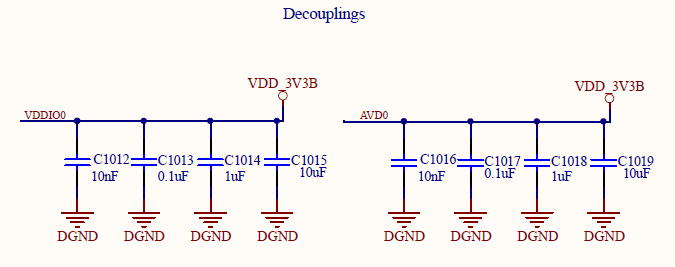
    Additionally, can you share a screenshot of the decoupling strategy used on each supply?

    Thank you,

    Nikhil

  • Hi Nikhil,

    Nikhil Menon said:
    Additionally, can you share a screenshot of the decoupling strategy used on each supply?

    Please, find attached.

    Nikhil Menon said:
    Can you additionally, set the PHY in analog loopback, sending packets from the processor, to the PHY and back to the processor?

    Assuming I have a custom board booted using U-Boot, how can I send packets from the processor and verify if they are back?
    What are the steps to perform this test?
    I know how to configure analog loopback on PHY, but I have no idea how can I force the processor to send and verify packets.

    Regards
    Adam

  • Hi Adam,

    Thank you for your patience. Setting the AM3352 to send and verify packets is outside of the scope of this forum. The processor team and forum will be able to help you with this setting. If analog loopback proves successful, this shows that data is able to be sent and received on both the cable side and MAC side and further debug will be necessary.

    Thank you,

    Nikhil

  • Hi Adam,

    Are you able to set the device in analog loopback? Please let me know if this is possible or if we should continue in another direction.

    Thank you,

    Nikhil

  • Hi Nikhil,

    Yes, I'm able to set PHY in analog loopback mode.
    Unfortunately, I have no idea how I can perform this test.

    I don't know how I can force the AM335x to interact with PHY via RMII to test this interface, assuming PHY is working in analog loopback mode.

    Regards

    Adam

  • Hi Adam,

    Setting the AM335x to generate and check packets in a loopback test is outside the scope of this forum. You may start an inquiry with the processors forum. If you have multiple EVMs handy, the following setup may be tried:

    EVM1 - cable - EVM2 back to back EVM3. (connect EVM2 and 3 via MAC pins in a back to back configuration)

    1. Set EVM3 for analog loopback

    2. Set EVM1 to set the PRBS checker into continuous mode and generate packets. (Register 0x16)

    3. Packets will be sent across cable to EVM2, across MAC pins to EVM3, looped back to EVM1

    4. Check PRBS error counter in register 0x1B to confirm no errors. 

    Thank you,

    Nikhil