This thread has been locked.

If you have a related question, please click the "Ask a related question" button in the top right corner. The newly created question will be automatically linked to this question.

ESD321: How to check a TVS clamping voltage against an IC absolute maximum ratings

Part Number: ESD321
Other Parts Discussed in Thread: TPD1E04U04, ESD351, ESDS312

Hello,

I have a data acquisition system for Wheatstone bridges. The sensors are external to the circuit, and connected to the ADC through an onboard connector. I experienced some ESD problems on the ADC and power lines on the circuit. Now I am redesigning my circuit, and I would like to add ESD protections on the ADC (and power) input lines.

I found some devices (ESD321 and others), but their clamping voltage is always higher than the ADC absolute maximum ratings. Usually, when I select a TVS diode I always check the following equation:

working voltage < VRWM < VBR < Vclamp < voltage absolute maximum rating

The ADC AMR is 5.3 V; I searched for alternate devices, but all have similar specs. ESD321 clamping voltage is 6.8 V, and other devices share similar clamping voltages. I thought about using a series resistor, but its power rating would be huge, and I'm not sure an ESD pulse could damage devices as it was a DC signal.

So, how to solve? Can AMR be relaxed when voltage on the pins has a very short duration?

Thanks in advance

Stefano

  • Hello Stefano,

    You are correct on your equation. If the AMR for the ADC is 5.3 V, I would not recommend having a clamping voltage any higher than that. With that being said, I did find another part that could possibly fit your needs. TPD1E04U04 offers the same Vrwm of 3.6 V and a lower clamping voltage of 5.3 V. Would this work for you?

    Regards,

    Matt Smith


  • Hi Matt,

    unfortunately TPD1E04U04 only has a 5.3 Vclamp rating at 1 A. At 16 A its rating from IO to GND is 8.9 V and this is higher than my ADC AMR. A quick comparison between TPD1E04U04 and ESD321 shows that at 16 A their Vclamp ratings are 8.9 and 6.8 V respectively, and, assuming they are linear, this would mean that ESD321 would have a lower Vclamp at 1 A (this is not shown in the data sheet). ESD351 has a slighlty lower Vclamp at 16 A (6.5 V), but it is still higher than AMR. Is there another solution? Perhaps a two stage solution could help?

    Thanks and regards

    Stefano

  • Hi Stefano,

    I would not advise combining multiple parts for ESD protection. If you have two diodes in parallel, the voltage will only clamp to the smallest of the two. In series, the clamping voltage would actually increase. 

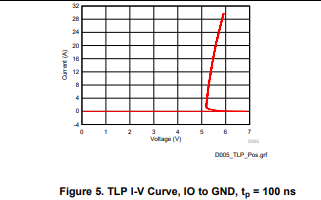
    I looked at our parts again, this time for an Ipp at 16 A. ESDS312 has the lowest clamping voltage at 16 A at 5.5V. You can see the behavior on this TLP curve below.

    Let me know if this answers your question.

    Regards,

    Matt Smith

  • Hi Matt,

    with ESDS312 clamping voltage would be safer than other solutions. But moving to breakdown voltage, I am wondering what would happen in case of ESD event. Breakdown voltage ranges from 4.5 to 7.5 V (I assume it depends on tolerances and ambient factors). During an ESD event, if the diode breaks down somewhere under 5.3 V, as current rises I can assume that voltage is safe because clamping voltage is under AMR. But what happens if during the ESD event breakdown voltage is above 5.3 V? This would violate AMR and possibly destroy my ADC. Or is duration too short?

    Thanks

    Stefano

  • Hi Stefano,

    This is due to what we call the snapback of the diode. If you look at the TLP curve above and also the breakdown measurement in the datasheet, it shows the diode breaks down at a maximum of 7.5 V at 1 mA. As soon as the current increases past 1 mA, the voltage snaps back and begins clamping. When an ESD event occurs, the current will be much higher than 1 mA, so you should, so your ADC should be safe. 

    Regards,

    Matt Smith

  • Hi Matt,

    ok, I think this solves my issue.

    Thanks again

    Stefano