This thread has been locked.

If you have a related question, please click the "Ask a related question" button in the top right corner. The newly created question will be automatically linked to this question.

DP83867CR: Failure with multiple PHYs sharing the MDIO bus

Part Number: DP83867CR
Other Parts Discussed in Thread: AM3352

Hello,

   We have a custom board with two TI DP83867 PHYs and a 3rd party switch chip sharing the MDIO bus.  We are seeing some intermittent behavior where one of the TI PHYs will go into a bad state and lose the link to the network.  When this happens, if we do a dump of the MDIO registers for this PHY, all registers show 0xFFFF values.  (Occasionally, we will see all registers show 0x1140 instead of 0xFFFF).  When the error occurs, we have to reset the phy or power cycle the board to recover.   I have discovered that if I put the second phy in power down state, the first phy no longer experiences these errors.  I've been probing the MDIO signals with a scope, and I see that sometimes there are data transitions on the mdio bus that violate the hold time of the phy.  Looking at the data sheet for dp83867, I found the following timing parameters:

7.8 MII Serial Management Timing(1)
See Figure 3.
PARAMETER                                       MIN NOM MAX  UNIT
T1 MDC to MDIO (output) delay time      0                10      ns
T2 MDIO (input) to MDC setup time       10                         ns
T3 MDIO (input) to MDC hold time         10                         ns
T4 MDC frequency                                        2.5       25      MHz

It looks like the clock to data delay time for read data returned by the phy will be between 0 - 10 ns.   But, the required hold time is a minimum of 10 ns.  If we have two DP83867 phys sharing the same mdio bus, will the output of one phy violate the timing parameters of the other phy?  On the oscilloscope, I am seeing clock to data timing as small as 5 ns.  I've confirmed that the data transitions with ~5ns delay are coming from the DP83867's.  Also, disabling the second phy will result in the first phy not experiencing the error.  So, I am suspecting some interaction between the two phys.

Given the timing numbers above, is it ok to have two DP83867's share the same MDIO bus?

Thanks,

Gavin.


  • Hello Gavin,

    How do you disable the other 867 phy?

    For MDC/MDIO timing matters only between controller (origin of MDC) and the addressed phy. So one phy's timing should not be interfering with other phys timing parameters.

    Are the strap values for phy address on these 2 867 phys as per datasheet recommendation?

    Does this issue happens only after power-up? Or without power cycle also phy's data is becoming good to bad? If it is related to power-up, then do check the power up timing recommendations in the datasheet.

    Do you have an external oscillator as clock input to XI or is there a crystal attached to each phy?

    --

    Regards,

    Vikram

  • Vikram,

        I disabled the other phy by asserting the PowerDown signal.  I have several boards that I am testing.  Some of the boards never fail.  One board was failing relatively often.  When I put the other phy in power down state, the failure stopped happening.  I left the board in this state for several days, and no failure.  I then did a wakeup on the second phy and re-established the network link.  The failure started happening again.  

    The failure is a random link down failure that happens after the board is powered up.  We have a script running that will attempt to bring the link back up when it goes down.  It does this by resetting the phy.  It doesn't always work.  If I leave the board running, I can see logs of link down events.  These link down events can happen after 5-10 minutes sometimes.  Or, the board can be ok for several hours before failing.  I have left the board running for many hours and see link down event during this time.

    One other piece of information - I had wires attached to the MDIO signals so that I could connect an MDIO protocol analyzer.  With the wires attached, the failure did not occur.  When I removed the wires, the failure started occurring again.

       I used a scope to look at timing of the MDIO data signal relative to the MDIO clock.  The MDIO master is an AM3352 TI processor.  When the processor drives data on the bus, the data transitions near the falling edge of the clock.  So, plenty of setup and hold time.  When the phys or switch are driving read data onto the mdio bus, data transitions near rising edge of mdio clk.  In some cases, the clock to data delay is around 9 ns.  In other cases, it is as small as 5 ns.  I was able to use the oscilloscope to capture fully transactions, and confirmed that the dp83867 phys are driving the data when the delays are around 5 ns.  

    MDIO timing will affect the controller and the addressed phy.  But, all phys are looking at the bus.  So, a violation of hold time could affect how other phys are interpreting the data on the bus.  

    We have strapped the two phys to have different phy addresses.  One phy is at 0xC and the other is at 0xF.  

    The failure is not at powerup.  It is occuring long after powerup.  After powerup, the board will operate normally - for a while. 

    We are using separate 25 MHz reference oscillators for each phy.  The MDIO clk signal is common between the phy devices, though.  

  • Hello Gavin,

    Do you have the control over the reset pins of the phys? Please also share the MDC/MDIO waveforms you described and I can get it reviewed/confirmed with team here : with and without cables attached? 

  • Vikram,

      I do have control over the reset pins to both phys.  The phys are reset prior to bringing up the links. 

    I don't have pictures from when the wires were attached.  The pictures below are without the wires.  

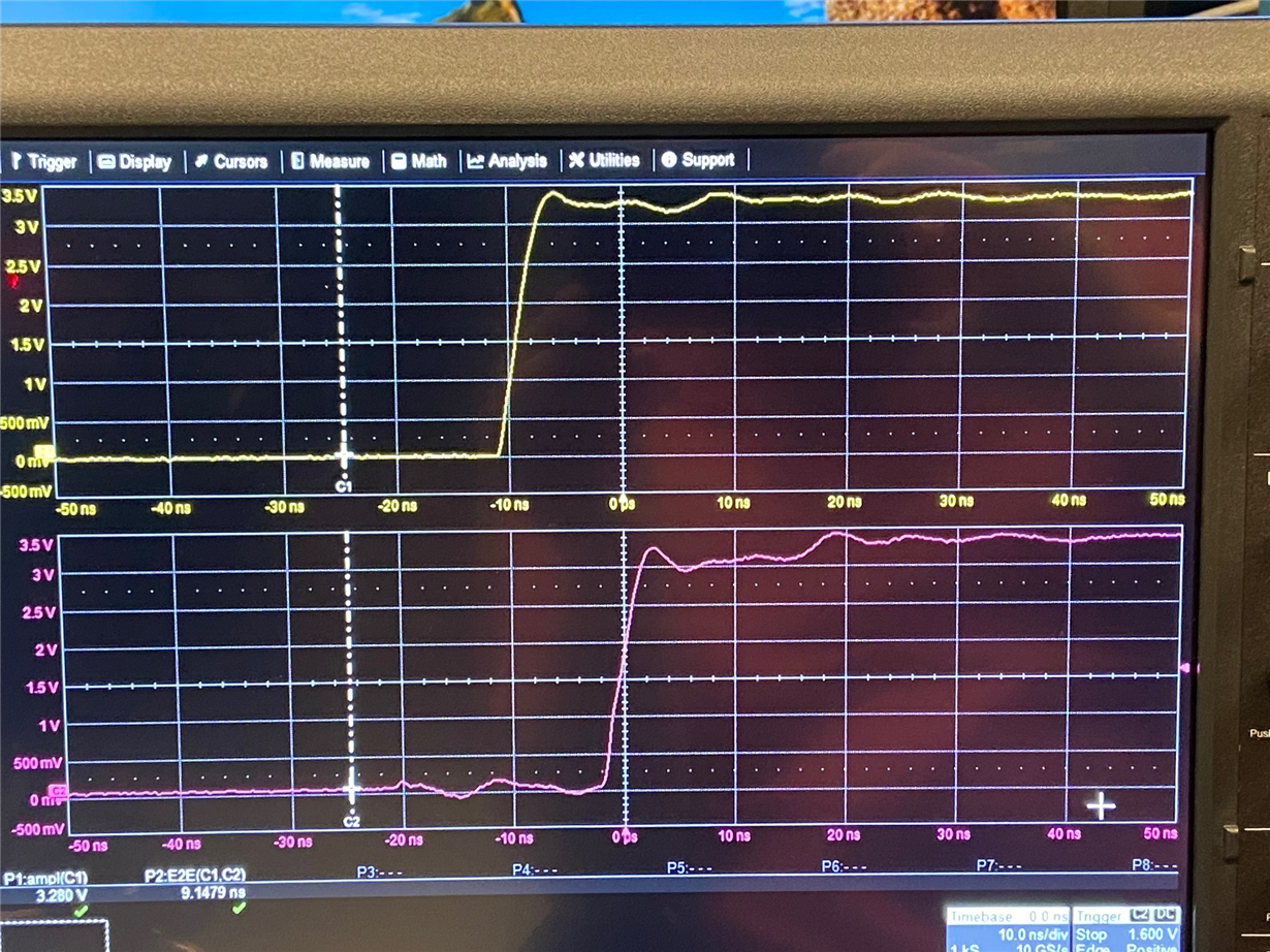
    This first image shows clock to data delay of around 9 ns.  One of the devices on MDIO bus (probably the switch) is driving read data with this kind of delay. The top (yellow) signal is clock.  The bottom (purple) signal is data. 

    Here is another signal capture. In this case, the clock to data delay is just over 5 ns.  I was able to capture a full transaction and verify that read data from phy 0xF and 0xC have delays like this. These phys are dp83867's.

    Below is a capture of a mdio read to phy addr 0xC.  You can see in this capture that the MDIO master drives data near falling edge of clk, while the read data transitions near the rising edge.  In this picture, yellow is clk and blue is data. 

    Below is a capture of a mdio read to phy addr 0xF.    

    We see link failures on phy 0xC sometimes.  As mentioned earlier, if I disable phy 0xF, the failures on 0xC do not occur.  I have seen clock to data delays as small a 5.0 ns.  The required hold time for dp83867 per the spec is minimum 10 ns.  

    gavin.

  • Gavin,

    I am reviewing the shared data with team here and will get back to you soon.

    --

    Regards,

    Vikram

  • Vikram,

      Do you have any updates?

    Gavin.

  • Hello Gavin,

    It is taking sometime to get the feedback. I am following up with team but looks like we will need time till early next week.

    --

    Regards,

    Vikram

  • Hello Gavin,

    We found that putting 867 PHY in power-down mode does not stop its activity on MDIO lines. Hence if for any reason MDIO of one phy was interfering with other, then putting one of the PHY in power-down should not have resolved the issue. So is it just the toggling of power-down pin or some other pin is also toggled for power-down mode? Is some power supply for this phy is also shut down in power-down mode?

    --

    Regards,

    Vikram

  • Vikram,

      Putting the PHY in power-down mode does not disable the MDIO interface.  But, it does cause the link to be down, and changes the MDIO accesses made by the driver.  We believe accesses to one PHY is causing issues with the other PHY on the same bus.  Its possible that the same thing can be accomplished by keeping the link down.  But, we had easy access to the power-down signal.  So, we tried that.  To put the PHY in power-down mode, we only assert the signal to the PHY.  Nothing is done to the power planes/supplies.  The behavior we observed was that eth1 was having link down issues, but after putting eth0 in power-down state, the issues stopped happening.  I was able to repeat this a couple times.  Note that the eth0 link connects to an onboard switch.  But, there were no devices connected to this switch when we ran the tests.  So, there is no ethernet traffic on eth0.  The other important piece of information is that the link-down events also stopped happening on eth1 after we attached probe wires to the MDIO bus.  The probe wires were added to connect an MDIO protocol analyzer.  But, even with the analyzer not attached, the eth1 link down events stopped happening.  So, having a couple of wires attached to the MDC and MDIO signals caused the failure to not happen.  This type of behavior suggests timing issues, or something like that.  I spent some time probing the signals with an oscilloscope.  It should be noted that when the TI processor is driving the MDIO bus, it drives data transitions on the negative edge of the clock.  So, this makes it virtually impossible to have timing issues on mdio - there is very large setup and hold time when data is driven on the negative edge of clk.  But, the read data from the phys and from the switch are driven onto the mdio signal using the positive edge of the clock.  So, any timing issues would have to be caused by the phys or the switch driving read data onto the bus.  The hold time requirement for the PHYs - from the TI datasheet - is 10 ns.  The switch drives data onto MDIO with a clock to data delay of around 9 ns or larger.  The eth0 and eth1 phys drive data onto the MDIO bus with a clock to data delay of 5 ns - sometimes I even measured slightly less than 5 ns.  So, my question at the start of this thread is whether there is an issue with having two TI phys share a common MDIO bus given that the clock to data output delay of the phy violates the hold time requirement specified for the phy.  Have you been able to find out anything related to that question?  Can you comment on the expected behavior of the phy if it sees data transitions on the MDIO that violate its hold time requirement?  

  • Hello Gavin,

    - There is no issue with multiple 867 PHYs on MDIO line. It is a common use case.

    - As I mentioned, putting PHY in power down mode does not change anything on its MDC/MDIO interface. So both PHYs would continue to act on MDIO the same way as they were before you put one PHY in power down. Thus we do not think that one PHY is causing timing violation in other PHY.

    -  We looked at the condition when one PHY will respond to something because of timing violations. If one PHY which is not addressed to during MDIO access has to inadvertentaly respond to request for another PHY address, it has to latch start bits(2bits), read (2bits), address (5bits) as a particular pattern. It is unlikely. And as explained in above point power-down of one PHY resolving the contention indicates that one PHY is not disturbing the other PHY directly with MDIO pulses.

    So in parallel may be we should start looking at something else. Is it possible to share the schematic to see how else power down of one PHY may improve the condition for another PHY?

    Also I agree with your hypothesis that if putting wire on MDIO is causing the fail to pass then somehow MDC/MDIO is contributing to the issue. If not because of timing then may be because of slower MDC/MDIO some cross-talk is getting reduced. So if possible we may look at XI, Rbias, MDC,MDIO board routing to see if MDC/MDIO is disturbing reference clock or rbias by them going close to each other .

    --

    Regards, 

    Vikram

  • Vikram,

       My responses are below.

    - There is no issue with multiple 867 PHYs on MDIO line. It is a common use case.

    [GZ] The MDIO bus protocol supports multiple PHYs.  The 867 user guide indicates that it supports sharing of MDIO across multiple PHYs.  We understand that this is a common use case.  We designed our board with multiple PHYs on the MDIO, and did not expect to have issues.  But, we are seeing an MDIO issue that we are trying to understand.  

    - As I mentioned, putting PHY in power down mode does not change anything on its MDC/MDIO interface. So both PHYs would continue to act on MDIO the same way as they were before you put one PHY in power down. Thus we do not think that one PHY is causing timing violation in other PHY.

    [GZ] Putting the PHY in power down mode does not disable the MDIO interface on the PHY.  It remains enabled and the registers are accessible during power down.  The user guide for 867 explains this.  I verified that the registers are accessible during power down several weeks ago.  But, when the PHY is in power down mode, the ethernet link is down.  This causes the register contents to be different.  It also causes the driver to do a slightly different sequence of transactions on MDIO.  So, there are differences on MDIO when the eth0 PHY is in power down mode.   

    -  We looked at the condition when one PHY will respond to something because of timing violations. If one PHY which is not addressed to during MDIO access has to inadvertentaly respond to request for another PHY address, it has to latch start bits(2bits), read (2bits), address (5bits) as a particular pattern. It is unlikely. And as explained in above point power-down of one PHY resolving the contention indicates that one PHY is not disturbing the other PHY directly with MDIO pulses.

    [GZ] I have been doing a lot of testing of the link down events on eth1 PHY.  I am seeing 3 cases where the ethernet link goes down. 

    Case 1: I can dump the MDIO registers for eth1, and see that almost all of them have expected values.  But, one register, 0x10, has the value 0xFFFF.  This is not the correct value.  If I write value 0x1048 to this register (the normal value) the ethernet link is able to come up, and the PHY behaves normally.  It appears that value 0xFFFF was written to this register for some reason.  I can manually reproduce this issue by writing 0xFFFF to register 0x10.

    Case 2: I can dump the MDIO registers for eth1, and see that all registers report the value 0x1140.  The ethernet link is down.  The PHY MDIO register values cannot be changed.  They are stuck at 0x1140.  Doing a reset to the PHY does not clear the issue.  The only way to recover from this case is to power cycle the PHY.  After power cycle, the phy is ok and the link comes up.  I discovered that I can manually reproduce this issue if I write 0xFFFF to MDIO register 0x0. 

    Case 3:  I can dump the MDIO registers for eth1, and they all report the value 0xFFFF.  The ethernet link is down.  I cannot change the values of the MDIO registers - they remain stuck at 0xFFFF.  Doing a reset to the PHY will clear this issue.  After the reset, the link will come up and the PHY behaves normally. I have not discovered how to manually reproduce this issue.  

    The eth0 and eth1 867 PHYs are connected to a TI processor.  The TI processor is running Linux, and we are using standard drivers for the ethernet stack.  I used an MDIO protocol analyzer to capture traffic on the MDIO bus.  It turns out there is a lot of traffic on this bus.  There is some process running that is doing a continuous scan of all PHY addresses, reading register 0x1.  This scan happens repeatedly and continuously.  Most PHY addresses have no phys, and the transactions time out with no response (MDIO remains high, 1'b1).  Mixed in with this scan are some other MDIO accesses to eth0, eth1 and the phys in the onboard switch.  The only writes on the MDIO bus that I observed are ones that we generate to the pseudo phy on the switch.  All other transactions are reads.

    Given that I can reproduce two of the three failure cases by writing 0xFFFF to an MDIO register on eth1, one of our suspicions is that eth1 thinks that it is seeing writes of 0xFFFF to its registers.  Also, the problem does not occur if the probe wires are attached to the MDIO bus.  The failure also will not occur if eth0 link is down (power down).  Our board has zero ohm series resistors added to the MDC and MDIO lines, close to each phy and to the switch.  I have replaced the zero ohm resistors on the failing board with 33 ohm resistors, and the problem has also gone away with this change.  It appears there is some timing issue or signal integrity issue that is causing eth1 to think it is seeing writes of 0xFFFF to its registers, even though this write does not exist. It is conceivable that a data pattern could be misinterpreted as a start of a transaction by the PHY.  The start bits for MDIO is just 01.  This is not a unique pattern. Once the PHY thinks it has seen a start of transaction, it will start trying to interpret the bits following this.  So, some data patterns might get interpreted incorrectly by the PHY and cause unexpected accesses to the registers.   

    So in parallel may be we should start looking at something else. Is it possible to share the schematic to see how else power down of one PHY may improve the condition for another PHY?

    [GZ] Putting eth0 in power down mode is just one way the issue goes away.  I agree that there could be something else going on here. I am open to any suggestion.  I previously sent screen shots of the waveforms captured on the oscilloscope.  The waveforms look pretty good.  I don't see much ringing.  The rise/fall of the clock is smooth.  I don't see anything obvious wrong with the waveforms - other than the fact that some data transitions violate the hold time of the 867 PHY.   

    Also I agree with your hypothesis that if putting wire on MDIO is causing the fail to pass then somehow MDC/MDIO is contributing to the issue. If not because of timing then may be because of slower MDC/MDIO some cross-talk is getting reduced. So if possible we may look at XI, Rbias, MDC,MDIO board routing to see if MDC/MDIO is disturbing reference clock or rbias by them going close to each other .

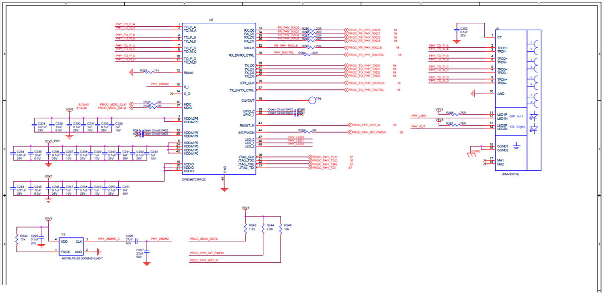
    [GZ] Crosstalk is something to look at.  As I mention above, the waveforms look pretty clean.  The XI pin on the chip is right next to the MDC pin.  So, these two signals will be close together for a short distance.  But, after the breakout from the chip, they are not close. Rbias pin is also very close to these pins.  Below is a screen shot of the phy circuit.  Is a fairly simple set of connections.  

    We have to figure out how to fix this issue across all our boards.  Adding 33 ohm series resistors did the trick on one failing board.  But, it is not clear if this is an overall fix, or if it just tweaked a failing board just enough to get it to work.