This thread has been locked.

If you have a related question, please click the "Ask a related question" button in the top right corner. The newly created question will be automatically linked to this question.

Compiler/TPS65987D: TPS65987D Souce 20V5A setting

Part Number: TPS65987D
Other Parts Discussed in Thread: TPS65987, TIDA-050012, TPS65981

Tool/software: TI C/C++ Compiler

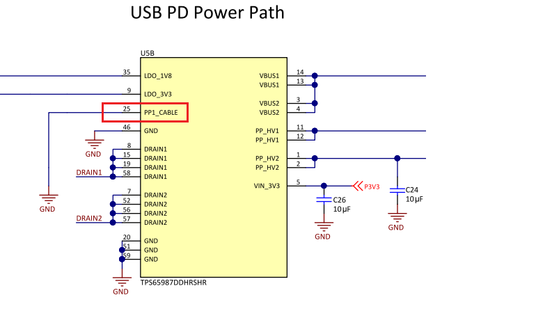
I want to supply 100W using TPS65987D.

I tried to supply using TPS65987 EVM, but it was negotiated at 20V3A.

I want to confirm setting
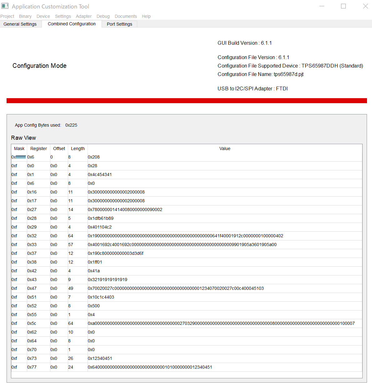
Is there a way to set "Type C Current" to 5A?

"Type C Current" on GUI was only Defolt,1.5A, 3A.

Best Regard

Kudo

  • Hello,

    Do you mean that you configured PD controller for 5A PDO but its making 3A contract only? if yes, please check if the cable is capable of supporting 5A (you can find out the cable capability from the datasheet of the cable or PD trace).

    Thanks

    Prajith

  • Hello Prajith san

    Thank you replay

    I was using the following cable
    www.mco.co.jp/.../
    UPD-220 / BK
    The package said it was compatible with 20V / 5A / 100W
    Can this Cable use ?

    I will list the confirmed PC.
    www2.razer.com/.../razer-blade-stealth
    razer blade stealth 13
    When I connected it from the AC adapter, it was 20V 4.2A.
    But from TPS65987EVM ,it was 20V2.7A.

    TPS65987EVM
    PP1 20V (external power supply)
    PP2 5A (DCDC_VAR)

    SW
    S1, S2 Defolt


    Could you please confirm the setting?
    Also, do I need to change the TPS65987EVM in terms of hardware?

    Best Regard

    Kudo

  • Hello Prajith san

    I attached Config setting

    Would you confirm this data?

    Best Regard

    Kudo

  • Hi Kudo-San,

    Please share the pjt file that you are using. 

    Thanks

    Prajith

  • Hallo Prajith san

    I try to upload pjt file .

    Would you confirm it ?

    If you can't confirm ,please teach me how to attach this prj file .

    Best Regard

    Shuji.kudo

    tps65987d.pjt

  • Hi Kudo-san,

    As I see" source PDO3 negotiated " in GPIO 20 event, but only two source PDOs is selected.

    Is the setting right with your hardware circuit?

  • Hello
    I used PC is 100W compatible .
    I don't use other PC.
    So I Prepared only 5V and 20V .

    20V to PP1
    5V to PP2

    By TPS65987EVM,I connected PP1 = SYS_VCC(20V) and PP2 =DCDC_VAL
    Is there a way to supply 20V 5A with this specification?

    Would you  possible to send a bin file or pjt file that can confirm 20V5A using TPS6587EVM?

    Would you tell me if we need to change hardware settinng by TPS65987EVM ?

    Best Regard

    Kudo

  • Kudo-san,

    You can try the latest .pjt file I attach, I have verified the .pjt and it can communicate 20V @5A successfully.

    I want to explain two points of this case.

    1. Since you use external power to power up 20V @5A, you don't need to set GPIO 20 event at PDO3. After the communication of PD, the 20V source path you map will be enabled automatically;

    2. The failure of 5A communication is caused by e-mark not powered. You used standard configuration template, which doesn't contain Vconn related configuration, so the e-mark was not powered, so the cable didn't tell PD controller its current capability @5A, and ultimately cause the 5A communication failure.

    In addition, I want to point out that your setting of GPIO20 @PDO3 will lead to error if you want use DCDC to generate 20V PDO.

    ---------------> You only configured two PDOs in "Transmit Source Capabilities" register, so the PDO with 20V @5A is PDO1 rather than PDO3; only if you configure four PDOs, you will use PDO3. And on TPS65987D EVM, the voltage level is determined by GPIO which will control the DCDC converter to send out the relative voltage level. We use GPIO14/ GPIO15/ GPIO17/ GPIO20 to generate 5V/ 9V/ 15V/ 20V. And actually 5V is generated naturally by DCDC output, GPIO14 is only used to light up the 5V indicator LED.

    In conclusion, the configuration you set makes no sense in this case because you use external power source (SYS_PWR) to generate 20V on VBUS. But if you want to use DCDC to generate 20V on VBUS, you need to set "source PDO1" on GPIO 20 rather than "source PDO3" because you just have set two PDOs to transmit source capability.

  • Hi Bing Hwang ,

    I check the Last Post , It say recommended to attach 5V to the PP_Cable pin. For VCONN  provide power to e-marked Type-C cables.

    Now I use Source Board is TIDA-050012, It seems connect PP_Cable pin to Ground, 

    If want to use e-mark need re-work on TIDA-050012 connect  PP_Cable pin attach 5V?

  • Hi , 

    I have same issue in TPS65987 , 

    When I set 20V 3A profile to 20V 5A. by Source Board(TIDA-050012) with pjt(TIDA-050012 Source Board) 

    Then using Sink Board(TIDA-050014) to Check Source Profile with "Received  Source Capabilities(0X30)",

    But the Receive Source Profile still show 20V/3A , Can help me please?

    (-----------My Device--------------)

    Source Board:  TIDA-050012

    Sink Board: TIDA-050014

    Type C Cable: E-Books

    TPS65981_2_6_7_8 Application Customization GUI Version : 6.1.1 

    Source Board Pjt File: 

    SourcePjt.pjt

    (1) When I connect  other type-c charger witch can provide more than  3A  to Sink board, then Check the register "Received  Source Capabilities(0X30)", it's  profile is correct  as Type-C Charger .

    (2) Is there any register in TPS65987 that  can check E-mark is on or not?  

  • Hi Les Lan,

    As the before thread I have explained, have you ever checked whether the cable can support @5A? Did VCONN has been established?

    These two items should be confirmed firstly if you want to establish a 5A PD power level successfully.

  • OK, let me take a look. Thanks.

  • Hi Les Lan,

    As the question is answered in other threads, please check and I would close this now.