This thread has been locked.

If you have a related question, please click the "Ask a related question" button in the top right corner. The newly created question will be automatically linked to this question.

TPS65982: DP-alt-mode Aux Channel voltage

Part Number: TPS65982
Other Parts Discussed in Thread: HD3SS460, TPS65988, TPS65987D, TPD6S300A

Hi,

our design uses a tps65982 as DP source and most DP sinks are working fine. However some of them have problems with aux communication (but the dp-alt-mode is negotiated successfully). In order to debug this we tested our design with a Unigraf UCD-340 DP Alt Mode Generator & Analyzer and that yielded incorrect voltage levels on AUX using the UCD-340's "AUX (SBU) lines test":

```

0000.000.001: Start test "AUX (SBU) lines test"
0000.000.068: USB ET cable contain 1 USB2.0 lanes
0000.005.512: Setup for straight cable orientation
0000.006.340: Disconnect CC lines for 1500 ms ...
0001.508.631: Set UFP role
0001.509.738: Connect CC lines
0001.509.783: Wait for DUT to be attached 10000 ms ...
0001.657.860: DUT attached
0001.657.906: Wait for DP Alt mode 5000 ms ...
0001.985.458: DP Alt Mode active
0001.985.505: Set HPD low to avoid AUX communication
0002.186.109: Measure voltage level on AUX+ line ... 1.581V
0002.329.159: Measure voltage level on AUX- line ... 0.007V
0002.481.897: Setup for flipped cable orientation
0002.482.728: Disconnect CC lines for 1500 ms ...
0003.990.288: Set UFP role
0003.991.396: Connect CC lines
0003.991.444: Wait for DUT to be attached 10000 ms ...
0004.127.838: DUT attached
0004.127.885: Wait for DP Alt mode 5000 ms ...
0004.455.151: DP Alt Mode active
0004.455.200: Set HPD low to avoid AUX communication
0004.656.129: Measure voltage level on AUX+ line ... 1.582V
0004.800.088: Measure voltage level on AUX- line ... 0.007V
0004.944.640: Test results:
0004.944.688:   Straight cable:
0004.944.788:     AUX+: 1.581V is out of range [0.100V, 0.600V]
0004.945.101:     AUX-: 0.007V is out of range [2.500V, 3.000V]
0004.945.365:   Flipped cable:
0004.945.464:     AUX+: 1.582V is out of range [0.100V, 0.600V]
0004.945.783:     AUX-: 0.007V is out of range [2.500V, 3.000V]
0004.946.047: Post test cable replug
0004.946.857: Disconnect CC lines for 220 ms ...
0005.167.551: Restore CC lines
0005.175.067: Test FAILED: "AUX (SBU) lines test"
0005.175.140: Error: 17:Incorrect voltage on AUX+

*** Test complete -- FAILED (Error code 17) ***

```

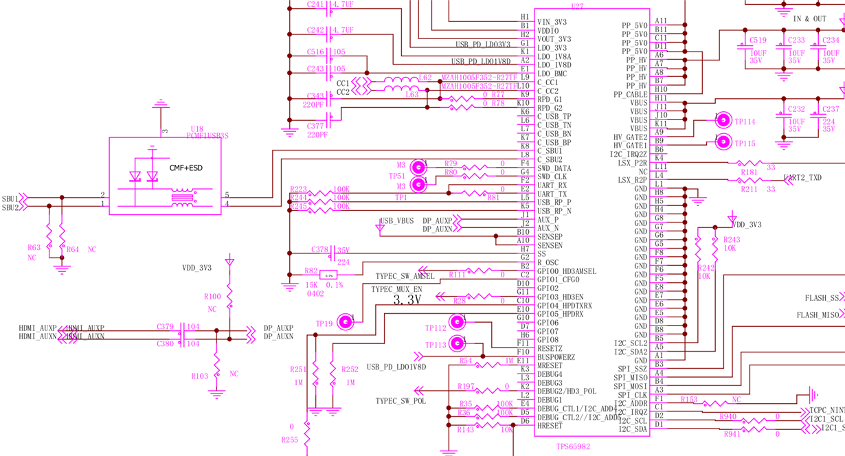
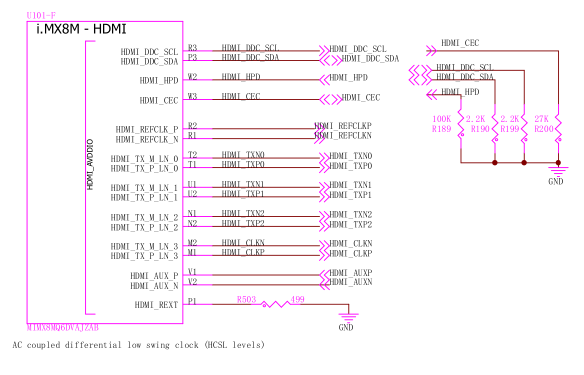
As per TI recommendation we have removed pullups/pulldowns from the DP_AUX lanes hence tps65982s J1/J2 go directly to the imx8MQ's DP_AUX_N/DP_AUX_P balls (called HDMI_AUX_P/HDMI_AUX_N there since the SoC can drive both DP and HDMI). What could be the problem here and what would you recommend to fix it?

Note: We've verified the that other DP-alt-mode sources not using the tps65982 pass the UCD-340's "AUX (SBU) lines test" as expected.  We also verified that the UCD-340's link training tests (DP_TX* is muxed via  TI HD3SS460 in our design) passes as expected on our design.

  • Hello, 

    Can you attach a schematic or reference design you are following?

    Please note that the TPS65982 is at EOL and is not recommended for new designs. The TPS65987D/TPS65988 are the next generation part recommendations. 

    Thanks,

    Emma

  • Hi Emma,

    here's the relevant parts from the schematics (parts marked as NC aren't populated):

    It's an existing design so we can't switch to other components except when they're drop in replacements (i'll open a separate question regarding upgrading recommendations) so we need to fix this existing one first.

  • Hello,

    Thank you for the schematic. Are you able to probe these lines and confirm that they are under voltage?

    Thanks,

    Emma

  • Hi Emma,

    > Thank you for the schematic. Are you able to probe these lines and confirm that they are under voltage?

    To avoid back and forth: Which points should be measured and what values should i expect? I can measure the SBU lanes but then that's what the UCD-340 measures already.

    (Also note that we have successfull DP communication with some Sinks)

  • Hello,

    Yes, please go ahead and probe those lines to confirm that the software is reading the hardware voltages correctly. 

    I will check internally with the team on what you are seeing here. Please allow a few days for review.

    Thanks,

    Emma

  • > Yes, please go ahead and probe those lines to confirm that the software is reading the hardware voltages correctly. 

    That was verified with other devices by the vendor (www.unigraf.fi/.../)

    > I will check internally with the team on what you are seeing here. Please allow a few days for review.

    Thanks, looking forward to that since TI suggested at e2e.ti.com/.../2400285 it's difficult to do that reliable.

  • Hello,

    Thank you for checking the software voltage readings. 

    From the log, it looks like the SBU lines are flipped? Can you follow the AUX connections and SBU connections from your DP source to the Type-C connector to ensure they are not switched anywhere?

    Thanks,

    Emma

  • Hi Emma,

    > From the log, it looks like the SBU lines are flipped? Can you follow the AUX connections and SBU connections from your DP source to the Type-C connector to ensure they are not switched anywhere?

    yes, we have verified these are not swapped. In an earlier design (which had pull-ups/pulldowns in the N/C positions of the schematic) voltage levels were swapped but those resistors were removed as per TI recommendation to give the tps65982 full control over pullups/pulldowns so cable flip can be handled properly.

    Looking forward to the voltage levels you expect us to measure.

  • Hello, 

    I am looking for the voltages expected in your testing:

    0004.944.788:     AUX+: 1.581V is out of range [0.100V, 0.600V]
    0004.945.101:     AUX-: 0.007V is out of range [2.500V, 3.000V]
    0004.945.365:   Flipped cable:
    0004.945.464:     AUX+: 1.582V is out of range [0.100V, 0.600V]
    0004.945.783:     AUX-: 0.007V is out of range [2.500V, 3.000V]

    The reason I still think that they are flipped is that AUX+ and AUX- reflect the voltage that the other is expected to be in both versions of your test, as shown above. Does your tester have flipped signals that you can check?
    Thanks,
    Emma
  • Hi Emma,

    I see that voltages flip together with the cable flip - hence I too thought  that routing might be wrong but we checked and didn't find that). We're checking this *again* over here to make sure there's nothing wrong with the routing (I keep you posted on that). But apart from that voltages are also consistently too low.

    Note that other DP sources we tested with the UC-340 all

    - reported voltages in the expected range of [0.100V, 0.600V] (Aux+), [2.500V, 3.000V] (Aux-)

    - correctly flipped voltage on cable flip (the cable flip is done by the tester automatically)

    > Does your tester have flipped signals that you can check?

    you mean that the tester itself might have SBU1/SBU2 swapped? No, the tester detects cable orientation and flips lanes internally for testing (verified with other devices as noted above).

  • Hello,

    I will wait to hear back on your double check of the routing. I would say this is our most likely point of error. 

    Thanks,

    Emma

  • > We're checking this *again* over here to make sure there's nothing wrong with the routing (I keep you posted on that)

    We've rechecked routing and again (both in schematis and on the actual PCB) and it looks correct.

  • Hello,

    Do you see this behavior on multiple boards? 

    Thanks,

    Emma

  • Hi Emma,

    yes, that was consistent over the boards we have at hand here.

  • Hello,

    In attempt to debug this issue, do you have the resistor option to change the wiring to switch the AUX+/- signals? I would like to rule out that switching the signals will not make a difference in this issue.

    Thanks,

    Emma

  • Hi Emma,

    > In attempt to debug this issue, do you have the resistor option to change the wiring to switch the AUX+/- signals? I would like to rule out that switching the signals will not make a difference in this issue.

    That would be difficult to do on the board. Is there a way to do mux AUX+/AUX- the opposite way via a firmware change instead?

    > Yes, please go ahead and probe those lines to confirm that the software is reading the hardware voltages correctly.

    Any news regarding the voltages we *should* measure (https://e2e.ti.com/support/interface/f/138/p/963822/3566153#3566153) ?

  • Hello,

    Please allow me a few days to look into this further.

    Thank you,

    Emma

  • Hi Emma,

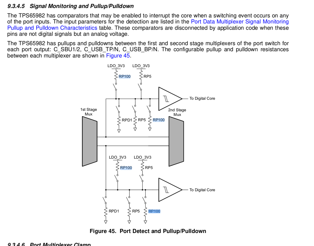
    sure. regarding the firmware modification it look as if pullups/pulldowns can be configured:

    but there's no further mention in the docs i could find *how* this can be done. Can you check for these details too please?

  • Hello,

    There is not a way to swap the mux via firmware. 

    The expected high voltage on the SBU lines are between 2V and 3.3V and the expected low voltage is 0-0.8V. 

    In order to verify on the hardware that the lines are not crossed please perform the following continuity verification:

    - Measure SBU1's voltage at the connector, then check the voltage at the EMI filter, to the PD controller, and at the AUX on the output of the PD controller. 

    Please perform the following verification on SBU1 and SBU2 and let me know the result.

    Thanks,

    Emma

  • Hi Emma,

    I'll check these and report back. Thanks!

    It would still be great to know how pullups/pulldowns can be configured. Section 9.3.4.5 suggests this is possible but there are no details *how* this should be done. Can you help here too? Thanks in advance and a happy new year!

  • Hello,

    Great, I will await to hear back your report! I am checking with our firmware team, but I do not believe that these pullup/pulldowns are user configurable.

    Thanks,

    Emma

  • Hello,

    I heard back from the firmware team. In this case, “configurable” means programable by the FW, not user.

    Thanks,

    Emma

  • Hi Emma,

    here's what i got (U2 is the TPD6S300A):

    # Regular plug orientation

    Receptable U/V U2 (USB-C plug side) U/V U2 (tps65982 side) U/V
    A8 0.9 SBU1 0.9 SBU1 0.9
    B8 0 SBU2 0 SBU2 0

    # Flipped plug orientation

    Receptable U/V U2 (USB-C plug side) U/V U2 (tps65982 side) U/V
    A8 0 SBU1 0 SBU1 0
    B8 0.9 SBU2 0.9 SBU2 0.9
  • ...and here's the measurement directly at the tps65982:

    ```

    # regular pulug orientation (measured at tps65982)

    type-c side U/V SoC side U/V
    SBU1 0.9 DP_AUXP 0.9
    SBU2 0 DP_AUXN 0

    # regular pulug orientation (measured at tps65982)

    type-c side U/V SoC side U/V
    SBU1 0 DP_AUXP 0.9
    SBU2 0.9 DP_AUXN 0

    ```

    So (as initially assumed) SBU lanes are muxed on cable flip, lanes on PCB are routed correctly (not swapped) but voltages look swapped due to removal of the pullups/pulldowns on the SoC side (as per TIs recommendation). Emma, would you recommend to add pullups/pulldowns back on the SoC side (schematics are at the very beginning of this thread)?

    This thread indicates no pullups/pulldowns should be added.

  • Hello,

    I talked with the team, yes please add back in the pullup and pulldown. You should add a 100k pullup on AUX_N to 3.3V and a 100k pulldown on AUX_P to ground.

    Thanks,

    Emma

  • Hi Emma,

    With pullups added back voltage levels are in the range you suggested (which matches what the UCD-340 expects:

    * normal plug orientation

    plug U/V
    A8 0.25
    B8 2.8

    * upside-down plug orientation

    plug U/V
    A8 2.8
    B8 0.25

    Not marking as resolved yet since it would still be great to be able to control the pullups on the tps65982  for some in the field devices (i can open a separate form thread for that though).

  • Hello,

    The TPS65982 does not have the ability to have configurable pullups. The pullup/pulldowns we discussed earlier are only controlled by the firmware and cannot be user controller.

    Thanks,

    Emma

  • Emma Hoying said:

    The TPS65982 does not have the ability to have configurable pullups. The pullup/pulldowns we discussed earlier are only controlled by the firmware and cannot be user controller.

    maybe I misunderstand but wouldn't a firmware modification make it possible to use different (predefined) pullups?

  • Hello,

    The device firmware is not modifiable, as it is used for internal workings of the mux. It will not be able to be configured.  

    Thanks,

    Emma

  • Hi Emma,

    > The device firmware is not modifiable, as it is used for internal workings of the mux. It will not be able to be configured. 

    It's not what I have hoped for but answers my questions. Thanks fort the feedback over all those posts!