This thread has been locked.

If you have a related question, please click the "Ask a related question" button in the top right corner. The newly created question will be automatically linked to this question.

DP83822IF: DP83822 Ethernet Issue

Part Number: DP83822IF
Other Parts Discussed in Thread: AM3359

Dear Sir,

After analyzing the AM335x ICE board and AMIC ICE boards, I completed my new design using AM3359 for PRU ICSS solution(Dual Ethernet).

I have successfully booted the board but some ties Ethernet is not working properly.

Input power supply to the board: 12 V

Serial port for debug : UART0 (CP2102 chip is used to convert TTL to USB)

Scenario 1


Step 1 : Connect the 12V  power supply

Step 2 : Connect the serial port (debug)

If follow the above steps then my processor will boot properly and all the peripherals are working fine.

Scenario 2

Step 1 : Connect the serial port (debug)

Step 2 : Connect the 12V  power supply

If follow these steps, both the Ethernets are not working. Both the  phys are detecting  but the connection is not establishing. Tried to reset the boards (software reset and hardware reset) still no improvement.

Thanks in advance

Regards,

Dilrosh P S

  • Hi Dilrosh,

    I have a few questions:

    1. How is the serial port connected to on the PHY? Is it through the MDIO pins? Can you provide a schematic snippet or a diagram?
    2. In scenario 2, can you check the Reset pin and see if the PHY is in Reset Mode? Can you also check if the CLK pins on the PHY are outputting a clock signal?
    3. In scenario 2, are you still able to read and write to the PHY registers?

    Regards,

    Adrian Kam

  • Dear Adrian,

    1. Serial port is connected to UART0 not to Ethernet. We are using CP2102 to convert TTL to USB.

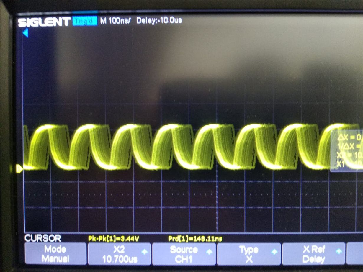
    2. In both scenarios reset pin is high. In scenario 2 the CLK pins have some disturbance please see the image below

    3. Yes in both scenarios we are able to read the phy registers.

  • Hi Dilrosh,

    I have a few more questions:

    1. Can you elaborate on what you mean by "the connection is not establishing"? Are you not able to link and send packets, or is the issue on the MAC side?
    2. For the clock signal, can you elaborate more on the disturbance? Are you referring to jitter? Also, is the clock signal 25 MHz?
    3. Can you provide a register dump?

    Regards,

    Adrian Kam

  • Dear Adrian,

    In the scenario 2 we are not able to make a connection to the network.

    1. If I give the command "ping 8.8.8.8" or try to connect to our local network packet loss happens. We are able to read the address of both phys and also able to read and write to all the registers of the phys.
    2. The clock is 25 MHz and in scenario 1 we are getting a correct waveform in TX_CLK and RX_CLK but in scenario 2 the clock signals both TX and RX clock are getting as shown in the previous message.
    3. Which register values required?

    Regards

    Dilrosh

  • Hi Dilrosh,

    I would like a register dump of addresses 0x00 to 0x1F.

    In addition, can you try the following experiment:

    1. In scenario 2, after conducting step 1 but before step 2, can you check the voltages on the pins of the PHY and compare them to when the PHY is not powered? Do you see any differences?
    2. Can you try the same thing as above with scenario 1? Do you see any differences? How does the results of this experiment compare to that of the one above?

    Regards,

    Adrian Kam

  • Dear Adrian,

    Register dumb details I will share you after interacting with my software team.

    1. In scenario 2, after step 1 checked the voltage rails and I am getting 0.969 V in the 3.3V section. This is the only difference I found while co-relating both the scenarios.

    I can share you the schematics of daughter card and master card (I can't share publicly) for your review.

    Please share the email ID.

    Regards 

    Dilrosh P S

  • Hi Dilrosh,

    Based on your finding, it seems the MAC side of the system is providing 0.969V to the PHY before you connect the power supply. This messes up the power-up sequence of the PHY and potentially causes issues. In scenario two, after step 1, can you try ensuring that the voltage is less than 0.3V? Once you have the voltage at less than 0.3V, try connecting the power supply and see if it works.

    If you are still having issues, send me the register dump, and you can email me the schematic. You can find my email by clicking on my E2E profile.

    Regards,

    Adrian Kam

  • Dear Adrian,

    I have shared the schematics through mail please go through it.

    If it is the voltage issue then after reset everything should work normal right? But in our case after providing reset still there is no success.

    Regards

    Dilrosh P S

  • Hi Dilrosh,

    I am in the process of reviewing your schematic and can provide you comments by EOD Friday at the latest. After you fix the voltage issue, go through the power-up process of scenario 2 again instead of resetting and see if it works. For reference, Figure 1 of section 7.21 of the datasheet shows a power-up diagram. As shown, analog power supplies should be initially below 0.3V. Your power-up timing should match the diagram.

    Regards,

    Adrian Kam