This thread has been locked.

If you have a related question, please click the "Ask a related question" button in the top right corner. The newly created question will be automatically linked to this question.

TCAN1042DEVM: TMS320F28379D

Part Number: TCAN1042DEVM
Other Parts Discussed in Thread: TMS320F28379D, TMS320F28388D

For running the  can_external_transmit on 28379d I am using two TCAN1042DEVM transceivers. The connections are as shown below:

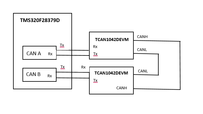
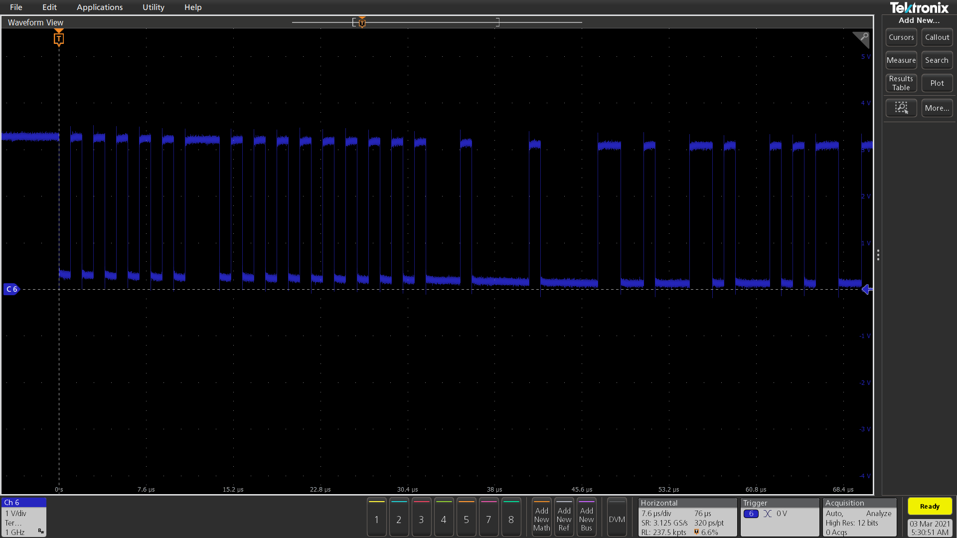
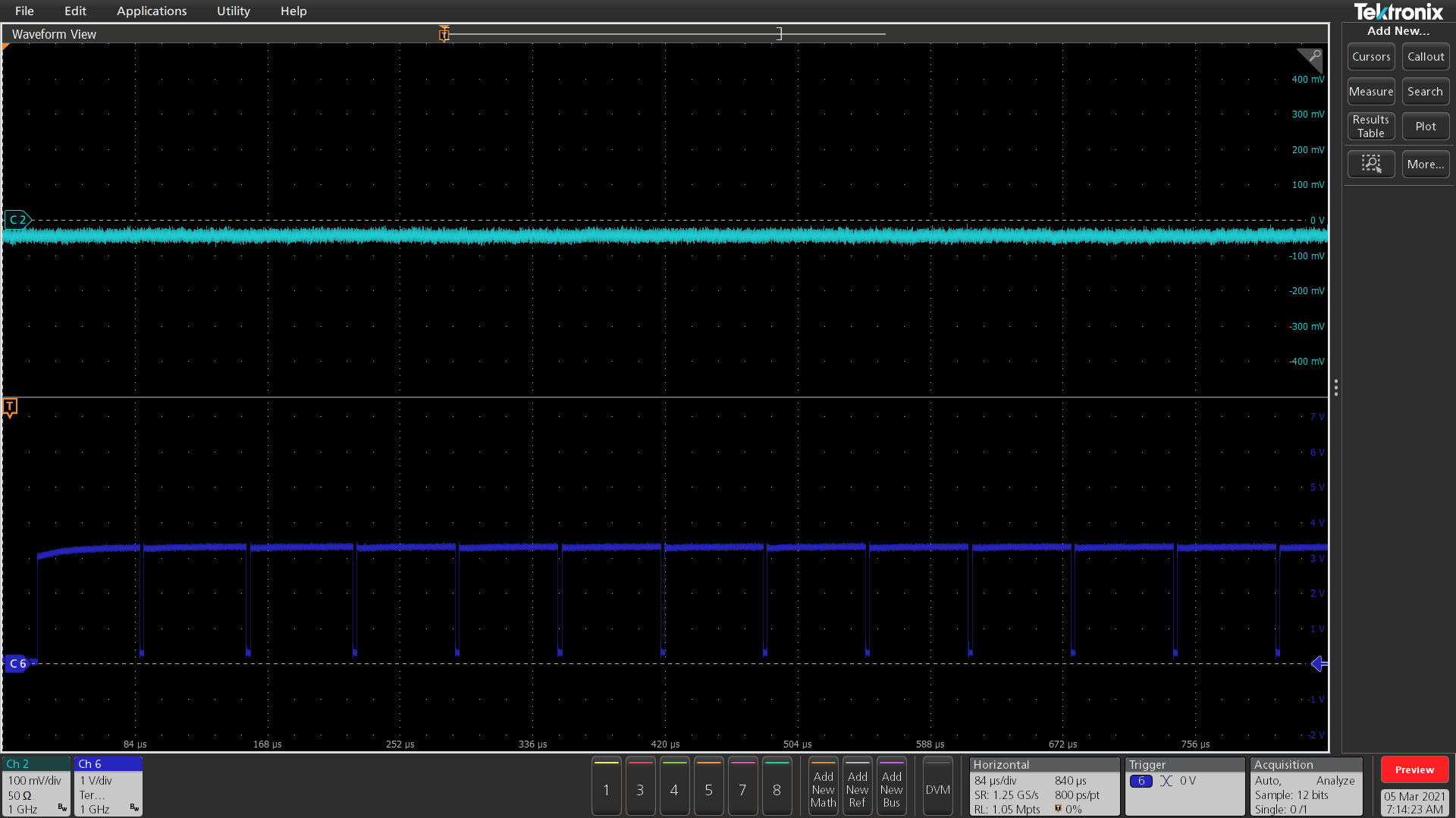
I have configured the GPIOs properly but do not see any receive operation and the errorFlag gets set. What are the configurations that are needed on these TCAN1042DEVM  for this to work?

  • Hi Snambiar,

    Since this is the transceiver forum, I'll focus on supporting and debugging this with a focus on the TCAN1042 transceivers and EVMs. If you have a question regarding the microcontroller, please visit the appropriate forum for expert help.

    For TCAN1042 to interact with the CAN bus normally, it will have to be in normal mode. This is acheived by driving the STB (pin 8) low (this pin has an internal pull-up, so while floating the device is in standby mode). The TCAN1042 EVM has a MODE jumper which can be used to control the state of this pin. While in normal mode, the RXD pin will reflect the state of the CAN bus and CAN driver will drive the bus according to the state of the TXD pin. 
    To identify if the transceivers are working properly, you can use an oscilloscope to view the digital lines (TXD, RXD) and CAN bus (CANH, CANL). This will where the communication is failing if it originates from this part of the system. 

    If you are able to verify that the transceiver is working properly, I can try to recommend debug methods for TMS320F28379D if you share how the system is currently configured. However, my experience with this controller is limited so my advice would likely be general and high-level. 

    Regards,
    Eric Schott

  • I am using 2 TCAN1042DEVM for this setup. I needed help with the JMP configurations. The current for both connections are:

    JMP1: PD mode

    I have removed the connections for JMP4, JMP 5 and JMP6.  Will this be causing an issue with the termination?

  • Hi Snambiar,

    JMP4 and JMP5 are used to control the termination used by the board. If two boards are used with CAN lines connected, each board can have one of these termination resistors connected. This emulates a CAN network with 120-ohms of termination at each end. Having no termination on the network could indeed lead to communication issues as the dominant-to-recessive fall time can be quite long. 

    JMP6 controls the voltage at pin 5. In non-V versions of TCAN1042, this pin is a no connect (NC), so the state of this jumper has no effect on the device. For V versions, this pin is Vio and is required for proper operation. Since this device needs to interface with a 3.3V controller, I would recommend use of a V version of this device, supplying Vio with 3.3V Vio. This can be done on the EVM by supplying 'P5' on JMP2 with 3.3V and leaving JMP6 disconnected. 

    Let me know if this works and if you have any more questions.

    Regards,
    Eric Schott

  • Hi,

    I am running a standalone test by just transmitting  some bits from the controller to the TCAN1042DEVM. I could see the packets being sent from the controller using a scope but nothing on CANH or CANL.

    I am providing 5V at Vcc.

    JMP6 is disconnected and a 3.3 V is given to pin P5.

    JMP1 is connected to PD

    JMP5 is open

    JMP4 is connected

    Do these connections seem right?

  • Hi Snambiar,

    Yes, these connections are correct and should put the device in a mode that will drive the CAN bus according to the state of the TXD pin. 

    • Is it possible that the device has been damaged prior to these tests?
    • Please confirm that the pull-down used on pin 8 has the appropriate resistor populated (R2 is DNP by default).
    • Have any modifications been made to the EVMs? Or are they in their default configurations (apart from the jumpers).
    • Is it possible to share the scope shots of the TXD line and CAN bus? I would like to ensure that the input voltages and timings are expected and see any activity that may occur on the CAN bus. Please include the location where the probes are connected to the board(s). 

    Regards,
    Eric Schott

  • Hi,

    I will get the scope images to you soon. When connecting both the TCAN1042DEVMs will there be an issue if the JMP6 is left open and no 3.3V is provided at P5?

  • Hi,

    I think the issue is no completion of transmission. The code stops working at :

    //
    // Poll TxOk bit in CAN_ES register to check completion of transmission
    //
    while(((HWREGH(CANA_BASE + CAN_O_ES) & CAN_ES_TXOK)) != CAN_ES_TXOK)
    {
    asm(" ESTOP0");

    I put in a counter to check and it stops after the first Transmisson. My setup for the TCAN1042 is the same as I mentioned earlier. 

    COMPLETE CODE

    #include "driverlib.h"
    #include "device.h"

    //
    // Defines
    //
    #define TXCOUNT 10
    #define MSG_DATA_LENGTH 8
    #define TX_MSG_OBJ_ID 1

    //
    // Globals
    //
    volatile unsigned long i;
    volatile uint32_t txMsgCount = 0;
    uint16_t txMsgData[8];

    //
    // Main
    //
    void main(void)
    {
    //
    // Initialize device clock and peripherals
    //
    Device_init();

    //
    // Initialize GPIO and configure GPIO pins for CANTX/CANRX
    // on module A
    //
    Device_initGPIO();
    GPIO_setPinConfig(DEVICE_GPIO_CFG_CANRXA);
    GPIO_setPinConfig(DEVICE_GPIO_CFG_CANTXA);

    //
    // Initialize the CAN controllers
    //
    CAN_initModule(CANA_BASE);

    //
    // Set up the CAN bus bit rate to 500kHz for each module
    // Refer to the Driver Library User Guide for information on how to set
    // tighter timing control. Additionally, consult the device data sheet
    // for more information about the CAN module clocking.
    //
    CAN_setBitRate(CANA_BASE, DEVICE_SYSCLK_FREQ, 500000, 16);

    //
    // Initialize the transmit message object used for sending CAN messages.
    // Message Object Parameters:
    // CAN Module: A
    // Message Object ID Number: 1
    // Message Identifier: 0x95555555
    // Message Frame: Extended
    // Message Type: Transmit
    // Message ID Mask: 0x0
    // Message Object Flags: None
    // Message Data Length: 4 Bytes
    //
    CAN_setupMessageObject(CANA_BASE, TX_MSG_OBJ_ID, 0x95555555,
    CAN_MSG_FRAME_EXT, CAN_MSG_OBJ_TYPE_TX, 0,
    CAN_MSG_OBJ_NO_FLAGS, MSG_DATA_LENGTH);

    //
    // Initialize the transmit message object data buffer to be sent
    //

    txMsgData[0] = 0x01;

    txMsgData[1] = 0x23;

    txMsgData[2] = 0x45;

    txMsgData[3] = 0x67;

    txMsgData[4] = 0x89;

    txMsgData[5] = 0xAB;

    txMsgData[6] = 0xCD;

    txMsgData[7] = 0xEF;

    //
    // Start CAN module A operations
    //
    CAN_startModule(CANA_BASE);

    //
    //Transmit messages from CAN-A
    //
    // while(1)

    //

    // Comment for infinite transmissions
    //
    for(i = 0; i < TXCOUNT; i++)
    //
    {
    CAN_sendMessage(CANA_BASE, TX_MSG_OBJ_ID, MSG_DATA_LENGTH, txMsgData);
    // CAN_disableController(CANA_BASE);
    txMsgCount++;

    //
    // Poll TxOk bit in CAN_ES register to check completion of transmission
    //
    while(((HWREGH(CANA_BASE + CAN_O_ES) & CAN_ES_TXOK)) != CAN_ES_TXOK)
    {
    asm(" ESTOP0");
    }}


    //
    // Stop application
    //
    //asm(" ESTOP0");
    }

  • Hi Snambiar,

    Both transceivers will need to be supplied with 3.3V to operate properly. The Vio supply is used to drive the RXD pin and is used as reference for the TXD input. The receiving device will need to be fully operational in order to translate the message back to the controller and send the corresponding acknowledgement. 

    Based on the code, I agree that it seems the transmission is never completed. Reading the full status of the Error and Status register (CAN_ES), particularly the Last Error Code (LEC, bits 2-0) will let us know what errors the controller has identified, if any. Could you share what the state of this register is after the message is sent? Viewing the waveforms will also help identify if there are any irregularities on the analog level. 

    Regards,
    Eric Schott

  • Hi,

    For a simple test using the above code I am using 1 TCAN1042 with the following configurations:

    5V VCC

    JMP1: PD , JMP2: 3.3 V at P5, Tx connected to Rx of MCU, Rx connected to TX 

    JMP4 : Connected ,JMP5: Open ,JMP6: Open

    CAN_ES 0x000000E5 Error and Status Register [Memory Mapped]
    PDA 0 Power down mode acknowledge
    WakeUpPnd 0 Wake Up Pending
    PER 0 Parity Error Detected
    BOff 1 Bus-Off State
    EWarn 1 Warning State
    EPass 1 Error Passive State
    RxOk 0 Reception status
    TxOk 0 Transmission status
    LEC 101 Last Error Code

  • Hi Snambiar,

    Thanks for providing the error status register state and confirming the board configuration. 

    I believe the problem is the TX and RX connections with the MCU. The CANx RX pin (MCU input) should be connected with TCAN1042's RXD signal (pin 4 output). The CANx TX pin (MCU output) should be connected with TCAN1042's TXD signal (pin 1 input). 

    The Last Error Code 0x5 is consistent with an incorrect connection. This code indicates that the RX input did not register dominant (logic low) when the TX output was driven dominant. In a proper system, a driven dominant should always appear on the RX line (it is possible that a dominant also appears on RX when TX is not driven). 

    With only one transceiver connected, another error is likely to be reported because the signal will not receive an acknowledgement. For the setup you describe with the correct TX/RX connections, I would expect the Last Error Code to be 0x3, indicating an Ack Error. 

    Let me know if this resolves the issue. 

    Regards,
    Eric Schott

  • Hi Eric,

    I made the connections as you suggested: CANx RX pin (MCU input) should be connected with TCAN1042's RXD signal (pin 4 output). The CANx TX pin (MCU output) should be connected with TCAN1042's TXD signal (pin 1 input). 

    The CAN_ES is still  0x000000E5. 

  • Hi Snambiar,

    Would you be able to capture and share scope shots of the bus (CANH, CANL) and the digital lines (TXD, RXD) during this transaction? It appears that the controller is reporting a loop-back error, so I'd like to check if the transceiver is able to properly drive the bus and what the state of the driving and receiving pins are at this time. 

    Regards,
    Eric Schott

  • Hi,

    My scope isn't capable of handling CAN. However the MCU has two CANs. When I try the code on CANB instead of CANA the error message changes.

    CAN_ES 0x00000007 Error and Status Register [Memory Mapped]
    PDA 0 Power down mode acknowledge
    WakeUpPnd 0 Wake Up Pending
    PER 0 Parity Error Detected
    BOff 0 Bus-Off State
    EWarn 0 Warning State
    EPass 0 Error Passive State
    RxOk 0 Reception status
    TxOk 0 Transmission status
    LEC 111 Last Error Code

  • Snambiar,

    Sorry for the delay here, our team has been very busy and will get a response to you tomorrow. Thank you for your patience.

    Regards,

  • Snambiar,

    It will be difficult to debug this from the transceiver perspective if we don't have oscilloscope screenshots of the CAN bus waveforms along with TXD and RXD. Since we aren't experts in the TMS device, it will be difficult to fully understand what is happening, but based on your last report of the error register is that there are no protocol errors occurring when you try the code on CANB. 

    I understand your scope can't decode CAN messages, but we just need to see the waveforms to understand if the CAN waveforms are propagating through the CAN bus at all. If you can get these oscilloscope shots it will make this debug much easier.

    Regards,

  • Hi Eric,

    I am still running the example code  "can_ex4_simple_transmit.c" and sending the data to TCAN1042DEVM. I can see a waveform at the Tx of CANA on the MCU  when running the code on the F28379D with no connection to TCAN1042DEVM, (Have attached the waveform below)

    However when the Tx and Rx of the MCU are connected to the TCAN1042DEVM, there is no waveform. I am checking at the same CANA Tx pin on both instances.

  • Snambiar,

    So when the MCU is not connected the waveform is present, but when you connect the input waveform to the TXD pin of the TCAN1042 transceiver, the MCU stops transmitting? Or there is just no waveform on the CAN bus? 

    What is the status of pin 8 when this is happening?

    Regards,

  • Hi Eric,

    I changed my MCU to a TMS320F28388D and the issue on no signal when connected to TCAN1042DEVM is gone. I connected a regular probe to the Tx of the MCU and a differential probe to the CANH-CANL. I didn't see any output on the TCAN1042DEVM CANH &CANL.

    The 1st signal is that of the CANH-CANL, while the lower one is of the Tx data from MCU.

    I also checked pin 8 at TP3. It remains at 0V throughout the operation.

  • Snambiar,

    The TXD waveform looks like an error frame, and since the CAN bus is not responding, thus RXD is not getting any information to send to the MCU, it will continue to send this error frame until it goes into BUS off mode. This is confirmed by your previous posts when you read out the error frame, but this still doesn't explain why CANH and CANL aren't responding at all.

    And just to make sure I understand, all you did was switch to a different MCU and CANH and CANL began to act as you would expect?

    Regards,

  • Hi Eric,

    Whenever I was connected the TCAN1042DEVM to the  TMS320F28379D MCU, the Tx from the MCU stopped completely.

    However when I switched to the  TMS320F28388D MCU the Tx did not stop even after connecting to the TCAN1042DEVM (Waveform shown in last post) 

    The CANH and CANL  of TCAN1042DEVM did not work for both MCUs. 

  • Hi Snambiar,

    The CAN Bus not responding to the signal at TXD makes it sound like the transceiver is not operating correctly. This may occur when a) the device is in standby mode (logic high input to STB pin 8), b) the device is in a protected mode due to thermal shutdown or an undervoltage condition on Vcc or Vio ('V' version of device), or c) the device is damaged.

    It seems we've verified that the device is not in standby (STB is 0V) and properly supplied (Vcc=5V) and I don't expect a thermal shutdown condition. This leads me to believe the device may be damaged in some way. To evaluate, could you try the following?

    • Measure the current being consumed by the device while idle and while (attempting) transmission. It should be a couple of mA recessive and several tens of mA dominant. If there appears to be excessive current draw in either state, it's likely the device is damaged.
    • Measure the voltage at CANH and/or CANL while the device is on, not in standby, and with no stimulus to TXD. The recessive voltage should be be around 2.5V (Vcc/2) on both pins.
    • Input a signal on TXD and observe the CAN bus to measure the dominant state. The output differential should be between 1.5V and 3V for typical 60-ohm loads. 
      • The input signal can be a square wave from a function generator. If this is not available, you can manually apply GND potential to the TXD pin (integrated pull-up will have device recessive before the manual dominant transition). Set the scope to trigger on either TXD or CANL's falling edge, or CANH's rising edge. Note that after the manual GND application, the device will soon return to the recessive state because of the dominant timeout feature. 

    If any of these tests aren't consistent with expected device behavior, the device may be damaged. I'd recommend changing the device out for a new one and repeating the tests to ensure that the issue is not board or setup related. 

    Also, I see that you are able to capture waveforms of the CAN bus. Note that CAN voltages in a closed system like this will not exceed Vcc. As we're concerned with analog behavior for this debug, the scope also does not need to be able to recognise CAN protocol. If the scope is capable of monitoring the 5V TXD and RXD signals, it will be able to monitor the CAN bus as well.

    Let me know if you have any questions about these steps and if I can clarify anything in the meantime.

    Regards,
    Eric Schott

  • Hi Eric,

    The issue was that I hadn't connected the GND of the TCAN1042DEVM Tx to the GND of the MCU baseboard. Once that connection was made everything worked perfectly. Thank you for all the help.